

You are using an out of date browser. It may not display this or other websites correctly.
You should upgrade or use an alternative browser.
You should upgrade or use an alternative browser.

s-petersen
Scott
something with cymbals and bells may reveal a difference
s-petersen
Scott
I sometimes think that even though they are beyond our hearing, the higher frequencies have an effect on the harmonics of the lower frequencies that we can hear.


Guys, I was thinking today about it and the UL120 has a solid state power supply, therefore the B+ arrives almost immediately at power on.
I was thinking added protection diodes between each grid/cathode of the 12AU7 (anode to grid) to protect the max grid/cathode when the tube is not conducting.
View? opinions?
Thank you.
I was thinking added protection diodes between each grid/cathode of the 12AU7 (anode to grid) to protect the max grid/cathode when the tube is not conducting.
View? opinions?
Thank you.

I sometimes think that even though they are beyond our hearing, the higher frequencies have an effect on the harmonics of the lower frequencies that we can hear.
Also on the phase response, at frequencies down to 3 octaves below the rolloff point. It's funny how sensitive the ear-brain system can be to phase-induced timing errors, sometimes...
Regards,
Gordon.

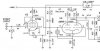
The 'AU7s will have full B+ applied to the grids at turn-on. This tube type has wide element spacing, but that's a lot of voltage. I don't know if they're all up to the task. As for protecting against this, I've never liked the diode approach except maybe in instrument amps. Diodes have capacitance in the off state, and it changes non-linearly with voltage. A better technique IMO is the use of a NE2 neon bulb. The bulb will fire for a few seconds when the amplifier is first powered up, then extinguish and become essentially inert. Below is a partial crop from the schematic of an amplifier I built recently. I thought about using diodes in series to reduce the capacitance, as well as low capacitance microwave diodes. In the end, I decided the neon bulb would be the most foolproof and least intrusive means of limiting the voltage.Guys, I was thinking today about it and the UL120 has a solid state power supply, therefore the B+ arrives almost immediately at power on.
I was thinking added protection diodes between each grid/cathode of the 12AU7 (anode to grid) to protect the max grid/cathode when the tube is not conducting.
View? opinions?
Thank you.
Jack
s-petersen
Scott
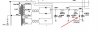
I used a P6KE300A TVS diode for one of mine, it worked perfectly. Mine started with a crackle until I added the diode. the diode was a 300v zener type diode meant to shunt transient voltage spikes, I used mine in the plate supply for the tubes' 300v supply The voltage is usually 295, and when it starts now, it starts at 305, until the tube conducts, I have pulled the tube for extended times to see if the diode gets warm, and it does not.Guys, I was thinking today about it and the UL120 has a solid state power supply, therefore the B+ arrives almost immediately at power on.
I was thinking added protection diodes between each grid/cathode of the 12AU7 (anode to grid) to protect the max grid/cathode when the tube is not conducting.
View? opinions?
Thank you.
Last edited:

trainbuftony
Electron Herder
Also on the phase response, at frequencies down to 3 octaves below the rolloff point. It's funny how sensitive the ear-brain system can be to phase-induced timing errors, sometimes...
Regards,
Gordon.
As humans we have a great set of sensory receptors for low bass feelings including phase. Not everyone realizes it but these hearing/feeling/sensing abilities were what allowed us to sense and react to danger and to determine weather it is coming towards us, away from us or may just stroll right by...
So it stands to reason a good music system that can reproduce those frequencies will have a better ability to stir our gut emotions than one which cannot reach 5+ octaves beyond typical human hearing.
The TO-600 is an overachiever, a show off, "hey look what I can do"
"Nobody asked you to do that"
"Ok you do it"
Crickets...

Brice -- This is just super, super work with stunning results, bringing such a rare unit from out of its ashes back to its original glory, and better. Reminds me greatly of the saga I went through with my ARC project.
I'm wondering about the performance results you posted for your ULIIs in post #30, and specifically the drop off in LF power response. If I'm interpreting the information correctly, the graph is indicating that just 30 watts is produced at 20 Hz. Even if the power curve is based on some undefined distortion standard, the drop off on the low end would seem excessive -- or am I missing something (always possible)? Any clarification of the conditions under which the two curves were generated would be appreciated if possible.
On the HF end, this unit uses a very unique form of NFB called Hybrid Feedback, where the tertiary FB winding is tightly coupled to both the primary and the secondary windings of the OPT (traditionally, tight coupling to just the primary winding was the main consideration for such windings), which then allows for a very high degree of closed loop load stability, and is a spotlight feature of the TO-600 transformers . Therefore, changes to the HF step network would in fact have only a minimal impact on load stability. The HF step network works in conjunction with the partially bypassed driver cathodes to produce the overall HF response of the design.
Thanks so much for sharing your odyssey in the restoration of such a landmark unit!
Dave
I'm wondering about the performance results you posted for your ULIIs in post #30, and specifically the drop off in LF power response. If I'm interpreting the information correctly, the graph is indicating that just 30 watts is produced at 20 Hz. Even if the power curve is based on some undefined distortion standard, the drop off on the low end would seem excessive -- or am I missing something (always possible)? Any clarification of the conditions under which the two curves were generated would be appreciated if possible.
On the HF end, this unit uses a very unique form of NFB called Hybrid Feedback, where the tertiary FB winding is tightly coupled to both the primary and the secondary windings of the OPT (traditionally, tight coupling to just the primary winding was the main consideration for such windings), which then allows for a very high degree of closed loop load stability, and is a spotlight feature of the TO-600 transformers . Therefore, changes to the HF step network would in fact have only a minimal impact on load stability. The HF step network works in conjunction with the partially bypassed driver cathodes to produce the overall HF response of the design.
Thanks so much for sharing your odyssey in the restoration of such a landmark unit!
Dave

In the end, I decided the neon bulb would be the most foolproof and least intrusive means of limiting the voltage.
also more period-appropriate. They wouldn't have used zeners when this was made, but certainly could have used a neon.
trainbuftony
Electron Herder
Brice -- This is just super, super work with stunning results, bringing such a rare unit from out of its ashes back to its original glory, and better. Reminds me greatly of the saga I went through with my ARC project.
I'm wondering about the performance results you posted for your ULIIs in post #30, and specifically the drop off in LF power response. If I'm interpreting the information correctly, the graph is indicating that just 30 watts is produced at 20 Hz. Even if the power curve is based on some undefined distortion standard, the drop off on the low end would seem excessive -- or am I missing something (always possible)? Any clarification of the conditions under which the two curves were generated would be appreciated if possible.
On the HF end, this unit uses a very unique form of NFB called Hybrid Feedback, where the tertiary FB winding is tightly coupled to both the primary and the secondary windings of the OPT (traditionally, tight coupling to just the primary winding was the main consideration for such windings), which then allows for a very high degree of closed loop load stability, and is a spotlight feature of the TO-600 transformers . Therefore, changes to the HF step network would in fact have only a minimal impact on load stability. The HF step network works in conjunction with the partially bypassed driver cathodes to produce the overall HF response of the design.
Thanks so much for sharing your odyssey in the restoration of such a landmark unit!
Dave
That is an odd one, Dave. I thoroughly tested my Acrosound 2s after rebuild and was able to chug out 4.5hz at 50 watts... I'd expect far more than 30 watts at 20 hz from these, considering the transformer is the same. Perhaps there was an error in measuring.
That's all I can conclude. The TO-600s are simply superb transformers capable of far more than the curve shows. Your results are much more in keeping with what I would expect on the low end from one of these units.
Dave
Dave
I used a P6KE300A TVS diode for one of mine, it worked perfectly. Mine started with a crackle until I added the diode. the diode was a 300v zener type diode meant to shunt transient voltage spikes, I used mine in the plate supply for the tubes' 300v supply The voltage is usually 295, and when it starts now, it starts at 305, until the tube conducts, I have pulled the tube for extended times to see if the diode gets warm, and it does not.
View attachment 2472151
View attachment 2472151
I like this idea, but are you sure the TVS doesn't get warm when the tubes are removed? A quick calculation indicates it will dissipate almost 1.3 watts.
Jack
s-petersen
Scott
I tried it for several minutes, the output tubes were in it, the phase inverter and preamp tubes were not.
The 33k resistor is dropping the 100v the Diode is dropping .9w according to the calculator
IIRC the diode is rated for 1W
The 33k resistor is dropping the 100v the Diode is dropping .9w according to the calculator
IIRC the diode is rated for 1W
Last edited:
According to the schematic, the 33K is dropping 140V. That means 4.24 mA is flowing through the resistor to the TVS. Dissipation in the TVS is 4.24 mA X 300V, or 1.27 watts. That particular TVS is rated for 5W max at 25°C, but I would still expect it to be hot to the touch.I tried it for several minutes, the output tubes were in it, the phase inverter and preamp tubes were not.
The 33k resistor is dropping the 100v