• The move to the new server is done. There are some software and database maintenance updates in process. This has us passing the hat around to help out. We appreciate any donations. Seriously, even a dollar helps. The payment page may be found here - https://www.audiokarma.org/support.html

Realistic Nova 8b Rebuild & Crossover Re-Design

Thanks for all the info regarding the crossover design. I was looking into this thread because my friend has a pair of the Nova 8's and was unhappy with the high frequency response. He bought these speakers new back in the 70's and can't seem to part with them. Unfortunately, he doesn't want to spend the additional cash to upgrade the crossovers, so I won't be able to see what all the fuss is about. I just don't understand those non-audio types. :sigh:

I did discover that one of the tweeters was fried and have ordered the re-issued phenolic ring tweeters from parts express to replace the originals. BTW, the 4-ohm version is on sale (46% off) now! I have my fingers crossed that these will fit without too much trouble... the hole dimension will be tight, although the flange seems to be just right.

After living with and seeing so many iconic speakers from the 1970's, I was pleasantly surprised to see the premium woofer that was used in this modest speaker, much like the 8b. It's nice to see a non-rotting surround on a fine cast alloy basket. I guess we know Radio Shack's marketing strategy for this speaker was to wow them with good quality bass.

I'll be watching with interest to see how the crossover upgrades progress. I may have to get my own pair of these bad boys to hot rod. :rockon:
 
Thanks for the info!

This is exactly what I came to AK looking for tonight. I haven't visited this forum for a while now, but have a pair of 8b's and have been wondering whether to sell them, or keep them in hopes of finding something about x-over improvements that might help the sound quality in these 35+ year old speakers. Thanks for all-o-the info on your mod.

The cabs are in great shape and the drivers are all original, but the mids and the highs have never been very pleasing. The mids have always seemed restrained and vocals nasally. There has always been a raspy quality to the mid to upper frequencies that has been displeasing. Seems that the mods you have come up with is a prescription for addressing both of these issues. This thread offers hope that I may have a diamond in the rough.

It may take a week or so for me to get the parts and get the mods done, but I do plan on making the suggested changes and will post once I have everything done.
 
Nova 8b Mods

This is exactly what I came to AK looking for tonight. I haven't visited this forum for a while now, but have a pair of 8b's and have been wondering whether to sell them, or keep them in hopes of finding something about x-over improvements that might help the sound quality in these 35+ year old speakers. Thanks for all-o-the info on your mod.

The cabs are in great shape and the drivers are all original, but the mids and the highs have never been very pleasing. The mids have always seemed restrained and vocals nasally. There has always been a raspy quality to the mid to upper frequencies that has been displeasing. Seems that the mods you have come up with is a prescription for addressing both of these issues. This thread offers hope that I may have a diamond in the rough.

It may take a week or so for me to get the parts and get the mods done, but I do plan on making the suggested changes and will post once I have everything done.

Sounds good! I think you will be very happy with them. What you have listed above is the same thing I heard and the reason I redesigned the crossovers in the first place!:thmbsp: Just a note, I bypassed the switches on the mid & tweeter. The new crossover wires directly to the mids & highs.
 
Installing the new crossover in the Optimus 5B

Phase 1 - Removing the old crossover

Tools I used:
- Phillips Screwdriver
- Flat Blade Screwdriver
- Pliers
- Wire Cutters
- Steak Knife
- Butter Knife

Getting Started:

Place the speaker cabinet on the floor, speaker side up
- Remove the grill (I use a butter knife at the edge, prying lightly)
- Using the Phillips Screwdriver, remove the woofer
- Disconnect the yellow wire and the black wire from the woofer
Set woofer aside in a safe place, you won't need this for awhile
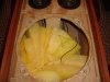
- Remove the fiberglass insulation, reserve it
I use pliers to grab it then put it into a plastic bag, itchy stuff!

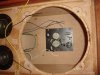
Now you can see the crossover. All the Black wires are ground wires
Yellow is the Woofer +
Blue is the Tweeter +
White is the Midrange +

You will also see a Green wire which is a jumper from mid to mid.
The Green wire does NOT connect to the crossover.
Leave it in place, no need to mess with it.

At the crossover, cut the Yellow, Blue, and White wires close to the crossover. (You'll need these later) Trace them back from the speakers. There is more than 1 White wire, for now just cut the one that goes to the midrange, cut it at the level adjustment pot.

Cut the 3 black wires close to the crossover.

Take out the 8 Phillips screws holding the crossover. Now you can remove the old crossover. Pull lightly around the edges. There is a gasket and it will tear as you take out the crossover. Don't worry about it. Get the old crossover out of the speaker cabinet.

If you have a suitable alternative to the plastic plate of crossover that you have just removed, use it to mount the new crossover.

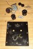
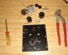
If you don't have an alternate 5 5/8" wide 6 5/8" tall mounting plate then you can remove the parts from the old crossover. This is what I did. Mostly it’s simple except for removing the old inductors. Those are a little tricky. You'll need the Steak knife (or pocket knife), the Phillips screwdriver, Pliers, and a Flat Blade screwdriver.

Connecting the old inductors to the plate is a Phillips head screw and a nut. The nut is flat on the top, this is a problem. Also there is a generous dab of glue on the threads of the screw to keep it in place.

First remove the glue from the threads. Scrape it away with the knife. If you are not comfortable with this, get some help. It is a knife and therefore dangerous.

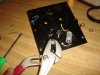
Once the threads are clean from the threads of both of the inductors, insert the Flat Blade screwdriver between the crossover and the bottom of one of the inductors. The purpose of this is to apply pressure up and keep the nut tight. Once you have some pressure on the inductor, use the Phillips screwdriver to loosen the screw from the rear of the mounting plate. Once it is loosened some, you can grab the nut with the pliers. Hold the nut with the pliers and continue turning the screw until it is out. Repeat for the other inductor.

Word of warning, doing this with 2 hands can be tricky. If you slip you might hurt yourself or anyone/anything in the area. If you are not sure how to do this, get some help or find an alternate mounting plate for your new crossover.

Remove the plastic knobs from the level adjustment pots. Using the pliers, remove the nuts from the level adjustment pots. There is a washer and lock-washer to take off once the nuts are removed. The pots are also glued to the crossover. Using the Flat Blade screwdriver, pry gently at the base and they should come loose. Never use the knife to pry.

The 3 capacitors are also glued to the crossover plate. Using the Flat Blade screwdriver, gently pry them loose. Also pry loose the 10 ohm resistor from the crossover mounting plate.

At this point you can take out the 2 level adjustment pots with the wires still connected to the 0.1mh inductor. Cut the wires for the other (1.0mh) inductor and the leads for any capacitors that are still connected.

Now just clean off some of the old glue that is still on the mounting plate and you should have a mounting plate that is ready for your new crossover.

That's enough for today. I'll mount the new parts tomorrow and post it.

//Smorgy
 

Attachments

  • DSC08227_sm2.jpg
    DSC08227_sm2.jpg
    92.5 KB · Views: 701
  • DSC08237_sm2.jpg
    DSC08237_sm2.jpg
    73.4 KB · Views: 572
  • DSC08252_sm2.jpg
    DSC08252_sm2.jpg
    94.7 KB · Views: 620
  • DSC08254_sm2.JPG
    DSC08254_sm2.JPG
    111.7 KB · Views: 757
  • DSC08271_sm2.jpg
    DSC08271_sm2.jpg
    94.7 KB · Views: 632
More Pics for the Optimus 5B speaker crossover removal.

This should be very similar on the Nova 8B speakers.

//Smorgy
 

Attachments

  • DSC08302_sm2.jpg
    DSC08302_sm2.jpg
    68.7 KB · Views: 531
  • DSC08299_sm2.jpg
    DSC08299_sm2.jpg
    84 KB · Views: 452
  • DSC08293_sm2.jpg
    DSC08293_sm2.jpg
    100.6 KB · Views: 455
  • DSC08273_sm2.jpg
    DSC08273_sm2.jpg
    114.5 KB · Views: 524
Smorgy - thank you for posting both the narrative and pictures of your crossover rebuild. Please don't spare the detail as I've never done this before and will need all the help I can get. :D

More Pics for the Optimus 5B speaker crossover removal.

This should be very similar on the Nova 8B speakers.

//Smorgy
 
Crossover rebuild for Optimus 5B continued...

Phase 2 - Installing the new parts

What you will need:
Solder
Soldering Iron
Phillips Screwdriver
Flat Blade Screwdriver
Wire Cutters
Pliers
Glue (I used Loctite Stick 'n Seal)
Hot Glue
Electrical Tape
All of the crossover parts mentioned early on in this thread
Digital Multi Meter (DMM)
Patience

I should have mentioned at the start of this to check each speaker for resistance. It’s a good practice anytime you have your speakers disconnected from the crossover. Bear in mind the midranges are tied together via the green jumper wire.

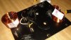
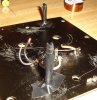
When I saw how much copper that was needed for this, I had to find a way to mount it securely on the mounting plate. I put the long screws back in that previously held the old inductors in place with one change - I put the flat side of the nut towards the mounting plate. Then I turned it all the way down to the plate and tightened it. This provided 2 posts which I used to mount the 2.0 and 1.0 mh inductors on. First I put electrical tape on the posts. I used 3 pieces in sequence to make a nice padded post. Then I used hot glue around the edge of the inductor. I was a little worried about this but it came out fine and I didn't over do it.

The holes that were in the plate for the old pots needed to be covered. I used a piece of plastic from an old "points" card from a hotel. It’s much like a credit card. I just cut a couple squares (ok - rectangles) and used the Loctite Stick 'n Seal to cover the holes.

The 2.7 mh inductor was too big to mount on the plate; I had to mount it to the speaker cabinet next to the crossover plate. I used the Loctite Stick 'n Seal on the bottom of the metal end and also put hot glue around the edge of the metal end of the inductor. After it set for an hour or so I could pick up the cabinet by lifting on the 2.7 mh inductor, so I felt confident that it would not fall off and end up in the bottom of the speaker.

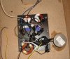
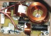
Once I had figured out how to mount all of that copper, I added the capacitors and the resistor, following the diagram available early in this thread. I didn't have any shrink wrap for the leads on the caps, so I just used electrical tape. I laid the wire of the cap in the middle of the piece of electrical tape and fold the glued sides of the electrical tape together. This sticks really well being glue on glue!

After soldering up everything that I could on the work bench, I put the crossover plate back into the speaker cabinet and connected up the big 2.7 mh inductor.

A basic thing to remember (since the mids and tweeters are wired out of phase) is that you will still have 3 wires connected to the positive post and 3 wires connected to the negative post. Follow the diagram.

At this point I will have to add that the diagram is mildly confusing concerning exactly where the 1.0 mh and 0.35 mh leads connect.

So, there, I did it. I put all the pieces in place and put the woofer back in. I connected up the newly upgraded speaker on the left channel and the stock speaker on the right channel so I could compare them directly.

Here is my feedback:

The only thing I am getting is sound from the woofer. No sound is coming from the mids or the tweeters. I have checked the wiring and, as far as I can tell, it is wired correctly.

It would be most helpful to see a picture of the original crossover so that I can compare mine to it and insure that I have it right. As it stands now, I am unable to progress until I can see that because I feel I have done all the steps and it’s unacceptable as is.

//Smorgy
 

Attachments

  • DSC08355_sm2.jpg
    DSC08355_sm2.jpg
    105.6 KB · Views: 734
  • DSC08328_sm2.jpg
    DSC08328_sm2.jpg
    65.9 KB · Views: 526
  • DSC08325_sm2.jpg
    DSC08325_sm2.jpg
    90.7 KB · Views: 491
  • DSC08320_sm2.jpg
    DSC08320_sm2.jpg
    126.5 KB · Views: 524
  • DSC08312_sm2.jpg
    DSC08312_sm2.jpg
    81.5 KB · Views: 574
I already have copies of the diagrams you posted. What I would like to see is your setup. Preferably with details easily viewable.

//Smorgy


Here are links to both the circuit diagram and the wiring diagram. If you can't get it working from these two, I would like you to remove the tape so I can see the connections and take a few more hi-res images. I will get you through this!:yes:


http://www.audiokarma.org/forums/attachment.php?attachmentid=218075&d=1277936451

http://www.audiokarma.org/forums/attachment.php?attachmentid=217638&d=1277681399
 
My Crossover Setup

I already have copies of the diagrams you posted. What I would like to see is your setup. Preferably with details easily viewable.

//Smorgy

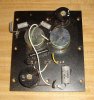
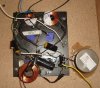
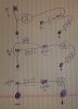
Attached are two images of my crossover. The first is just the crossover and the second has the path traced of each branch. Blue= Tweeter, White= Mids and Yellow= Woofer. I don't have the square drive here to take the crossover out, I would have to get it from work. You had said in one of your posts the wiring diagram wasn't quit clear. Can you let me know what part of it you don't understand.:scratch2:
 

Attachments

  • xovernova8b1.jpg
    xovernova8b1.jpg
    123.6 KB · Views: 889
  • xovernova8b2.jpg
    xovernova8b2.jpg
    126.7 KB · Views: 910
I have two pair (4) 7b's on their way. I know they're not the same as the 8b's but is there any post on improving the 7b's? If not, any plans?

Thanks
 
Attached are two images of my crossover. The first is just the crossover and the second has the path traced of each branch. Blue= Tweeter, White= Mids and Yellow= Woofer. I don't have the square drive here to take the crossover out, I would have to get it from work. You had said in one of your posts the wiring diagram wasn't quit clear. Can you let me know what part of it you don't understand.:scratch2:

I would like to say that your photos cleared everything up. But I can't. Even with the added color lines, its not clear to me.

Attached is what I have, Details are in the .ZIP files. (Removed ZIP files, See PDF files later in this thread...) Let me know where I went wrong with this please.

//Smorgy
 

Attachments

  • DSC08359_sm2.jpg
    DSC08359_sm2.jpg
    122.1 KB · Views: 663
  • DSC08363_sm.JPG
    DSC08363_sm.JPG
    82.2 KB · Views: 616
Last edited:
Crossover Wiring

I would like to say that your photos cleared everything up. But I can't. Even with the added color lines, its not clear to me.

Attached is what I have, Details are in the .ZIP files. Let me know where I went wrong with this please.

//Smorgy

Give me just a while to look it over and I will get back to you.:scratch2:

Your drawing is correct but I have to check your wiring in the picture.
 
Wiring Help

Originally Posted by Smorgy
I would like to say that your photos cleared everything up.

I found an issue that would keep the mids from working. The ground wire is missing going from the 2.7uf back to the terminals ground post. See the attached image. I can't see any other problems on the crossover in this picture. One issue might be that now with the reversed phase of the hi and mids both wires that you are now connecting to the T+ and M+ are now black. You may have them crossed which would leave you with an open circuit for each. Please add the jumper that is missing and check that the tweeter wires and mids wires (the black ones) are not crossed with each other.:scratch2:
 

Attachments

  • 8359_N8.jpg
    8359_N8.jpg
    99.2 KB · Views: 474
I found an issue that would keep the mids from working. The ground wire is missing going from the 2.7uf back to the terminals ground post. See the attached image. I can't see any other problems on the crossover in this picture. One issue might be that now with the reversed phase of the hi and mids both wires that you are now connecting to the T+ and M+ are now black. You may have them crossed which would leave you with an open circuit for each. Please add the jumper that is missing and check that the tweeter wires and mids wires (the black ones) are not crossed with each other.:scratch2:

Ok, I will add a jumper as indicated. I had it connected that way at first but was a bit confused on the wiring so I seperated those 2.

I have checked (and double checked) that the black wires are going to correct speakers. (mids and tweeter)

The .ZIP files show each speaker circuit in detail.

I'll solder that connection up and give it a try.

Thanks!
//Smorgy
 
The jumper brought the mids to life, which confirms the correct black wire is being used.

Tweeter is still missing in action. Please check the Tweeter.Zip file for complete details on the tweeter wiring.

Thanks!
//Smorgy
 
Tweeter Wiring

The jumper brought the mids to life, which confirms the correct black wire is being used.

Tweeter is still missing in action. Please check the Tweeter.Zip file for complete details on the tweeter wiring.

Thanks!
//Smorgy

I have tried to open the tweeter.doc file and can not. Word says it's corrupt. I would like you to check your tweeter with an ohm meter to be sure it works. I looked at you picture again and best I can see it is wired correctly. Let me know what you find.
 
Back
Top Bottom