• The move to the new server is done. There are some software and database maintenance updates in process. This has us passing the hat around to help out. We appreciate any donations. Seriously, even a dollar helps. The payment page may be found here - https://www.audiokarma.org/support.html

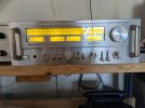
Received my Rotel RA-1312 today!!!!

I found one issue while refurbishing the phono board. Capacitor C411 appeared to be installed backwards according to the marking on the board. I compared the board marking with the schematic and the schematic confirmed that the board was mis-marked, an FYI for anyone else looking to work on this board in the RA-1312. The other thing is that the piece of blue wire which can be seen in the photo above was used to connect one side of C411 to R425. There is a break in the foil connecting these two points on the board which the blue wire corrects. The break in the foil was not very large so when I replaced C411 I left the positive lead long enough to bridge the foil gap and eliminated the blue jumper. It seemed a much neater way to go about it.

Here is a picture of the foil side of the phono board illustrating what I am referring to:
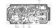
RA-1312 Phono Board.png

Not sure of the history of the jumper wire or the foil break.
 
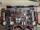
Here is a picture of the component side of the phono board after replacing all the caps and transistors:

PXL_20240327_005635352.jpg


I installed the board back in the RA-1312 and re-assembled the back panel. I tested the RA-1312 afterwards and the phono board is working fine.
 
After a break due to a Sciatica flareup I am back to working on the RA-1312.

One thing I noticed early on is that there is no DC offset adjustment on the RA-1312 like there is on the RA-1412. I am not sure why this is but if anyone has some insight into this I would appreciate hearing about it. I checked the DC offset and it is 0 Mv on one channel and 1.2 Mv on the other so that is good.

Back to the issue I have with the volume control. on the second and third detent I get some crackling noise when moving the control. It seems to subside once it is at rest at a given position but it troubles me. The other issue I have is that even with the -15DB attenuation switched in the granularity of the volume adjustment is less than optimal. It is either not loud enough or way too loud. Without the attenuation on it is too loud almost at the first detent.

My thoughts are to adjust the attenuation circuit to provide additional attenuation to both remedy the granularity of the volume control and to move the "standard" volume setting further up on the volume control to a position that does not have the crackling issue. That would eliminate the need to remove and disassemble the volume control which if I am not careful, rendering the RA-1312 inoperable.

My plan is to reverse the R506/504 and R505/503 resistors in the attenuator circuit to provide additional attenuation in the -15DB position without affecting the overall attenuation/volume circuit. The effect of the loudness setting on the output may be affected by this change but I can live with that.

I am attaching a picture of the circuit in question to this post for reference.

Any insight anyone may have would be appreciated before I proceed.


Ra-1312 Attenuation Board.jpg
 
Last edited:
Given I received no responses I disassembled the front panel of the RA-1312 and attempted to replace the R506/504 and R505/503 resistors I mentioned previously. It became apparent that the loudness/attenuation switches inhibited access to 3 of the resistors. I abandoned that plan of action and decided to fucus my next efforts ib rebuilding the power amp module and it's associated output transistors.
 
I unsoldered the power supply and pre-amp input leads from the power supply module and was able to remove it from the chassis assembly. It was not as daunting a task as I thought it might be. Here is a picture of the top side of the main amp board once I removed it from the chassis.

PXL_20240424_154319831.jpg

The topside was quite clean, however the underside has a sticky nicotine coating that was even worse than the phono module I cleaned earlier. I took a picture of the loveliness before I cleaned it. I is depicted below:


PXL_20240424_154541502.jpg

As you can see the board definitely experienced second-hand smoke.......

I spent over and hour and a lot of Q-tips cleaning up the board. I used solution of 99% isopropyl alcohol to clean the nicotine residue from the board. It is the same solution I use to clean excessive rosin from boards after I work on them. The picture is a sub-set of the Q tips used.....


PXL_20240424_163750008.jpg


I was very pleased with how the board looked after cleaning it. I wanted a clean board without the "Gunk" before replacing the capacitors and the potentially problematic transistors. Below is the board after it's alcohol bath.


PXL_20240424_162910951.jpg
 
I replaced all of the electrolytic caps and all of the 2SA750 transistors on the main amp board two days ago. I also removed and tested all eight output transistors. They all tested goof and were closely matched so using silipads I re-installed them on their heat sinks and re-installed the entire output amp assembly in the RA-1312.

PXL_20240428_142430810.jpg
 
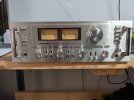
I then re-installed the front panel and knobs on the RA-1312 after cleaning everything. The amp is looking quite good and playing very well. The next thing on the agenda is to perform full power tests to align the protection circuitry settings which is always a bit exciting as they require you to operate the amp well beyond it's rated output. Here is a picture of the RA-1312 after re-assembly.

PXL_20240428_142548390.jpg
 
I performed the watts meter alignment yesterday which was pretty straightforward.

I also performed the Overload Protection level adjustment which was a bit more interesting. I get a bit concerned when operating and amp at or exceeding it's rated output which in this case is 80 watts per channel. As an initial test I connected and 8 ohm 100W nom-reactive load to both channels and fed in a 1Khz tone to the aux inputs. I used an oscilloscope to monitor the output as I do not have a Distortion analyzer. I drove one channel until it started to clip which was at approximately 100 Watts RMS. With both channels driven the amp started to clip at about 91 watts per channel. I was very pleased by these numbers. I ran the amp driving both channels at rated output to stress it and the output heat sinks got quite warm but not alarmingly so.

I then attached a 4 ohm 200W non-reactive load to the right channel to perform the overload protection level adjustment. As I did not have a distortion analyzer I drove the channel to the point it was obviously clipping which was at about 185 Watts RMS and adjusted VR602 until the relay disengaged. I then tweaked VR602 until the protection relay disengaged at the point where clipping just began to be seen which was at about 155 Watts RMS output. I then adjusted the left channel to go into protection at the same point. The heat sinks on the outputs became warmer still but were ok. This seemed like a reasonable method for me to use lacking a distortion analyzer.

Now all I have to do is put a coat of paint of the appropriate color on the top cover and Wrap things up!

I will now start working on the matching tuner......
 
This is an awesome writeup. I have had a ra 1312 for around 20 years now. Unfortunately, it is now in need of some service as I have intermittent static/ channel dropping out when playing at low volume. I was wondering if you had a parts list of the stuff you swapped? I can solder and would love to tackle this but I have no idea on what I should be swapping parts for. Would I be wrong in thinking the relay could be the cause of my issues? Any help you could provide would be appreciated.
 
A quick thing to check is to work the/unite/separate switch on the back of the amp several times and see if that affects the static/noise. That switch was an issue on my Ra-1312 and on the RA-1412 that I restored. It should be cleaned when you begin working in your RA-1312. You could also put the switch on "separate" and jumper the L/R amp-in/Pre-out together for each channel with short RCA cables to bypass the switch completely.

The RA-1312 has quite a few 2SC1222 and 2SA750 transistors that get noisy over time which I replaced when I restored mine. The relay could be an issue but I never had a problem there. I replace the relay as part of the restoration as part of the overall process. The power supply board containing the relay should be entirely re-capped as part of the restoration. There are a LOT of small "blue Blob" capacitors that should be replaced also.

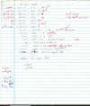
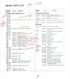
I would start with the power supply/protection board first and get that in shape and then proceed from there. I am attaching an annotated parts list with the transistor substitutions marked and a scan of the hand-written caps list I put together. Also attached a photo of the parts that I replaced excluding the main Filter capacitors.


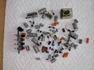
Rotel RA-1312 Caps list.jpgRotel RA-1312 Annotated Parts List.jpgPXL_20241223_141717555.jpg
 
Just want to say that you have made my day, the switch alone has fixed the majority of the problems. I didnt know about the switch and have suffered with the issue for years now. I had sprayed all of the front facing ones and could never get rid of all the static. In terms of brand is there one you would recommend more than others for the caps and transistors? Thank you so much.
 
I am glad I was of help to you! Feel free to ask me any questions.

Just about everyone used Onsemi transistors for restoration work. To replace the "Blue Blobs" use Wima film Caps, they are non-polarized unlike the Blue Blobs and are much higher quality. For the smaller electrolytics Nichicon are well regarded.

I am working on restoring the companion tuner for the RA-1312, the Rotel RT-1024. Completed the majority of the restoration, just a few more things to attend to and then an alignment. It already is playing beautifully.

PXL_20241223_193038163.jpg.
 
I finished restoring the Rotel RT-1024 tuner. I replaced all of the electrolytic caps and all of the "Blue Blob" caps in the unit and all of the 2SN1222 transistors which are known to get noisy. After the restoration I aligned the AM and FM/MPX sections of the receiver. The alignment was not too difficult though the charts indicating component locations were difficult to match to the physical components on the boards themselves. The FM RF/IF sections were off a bit but not too bad. The FM/MPX section was pretty much spot-on other that a slight tweak here and there. I hooked the RT-1024 to the RA-1312 for a final test together and the pair really sound nice together. I also paired the RT-1024 with a Fisher 400 using the 400 as an amplifier in this configuration and they really sounded great together, tube "warmth" combined with the RT-1024 as an excellent tuner was a nice combination. I am attaching a picture of the two Rotel's together. Now I have to decide what to do with pair.........

PXL_20250109_210619987.jpg
 
What did you decide to do about the volume control? In one of your early pictures I think there is a glimpse of what looks like a stacked multigang Alps potentiometer. Ben from Novaluxe had a youtube video out not long ago showing his disassembly and service of this unserviceable device, you should check it out.
 
I finished restoring the Rotel RT-1024 tuner. I replaced all of the electrolytic caps and all of the "Blue Blob" caps in the unit and all of the 2SN1222 transistors which are known to get noisy. After the restoration I aligned the AM and FM/MPX sections of the receiver. The alignment was not too difficult though the charts indicating component locations were difficult to match to the physical components on the boards themselves. The FM RF/IF sections were off a bit but not too bad. The FM/MPX section was pretty much spot-on other that a slight tweak here and there. I hooked the RT-1024 to the RA-1312 for a final test together and the pair really sound nice together. I also paired the RT-1024 with a Fisher 400 using the 400 as an amplifier in this configuration and they really sounded great together, tube "warmth" combined with the RT-1024 as an excellent tuner was a nice combination. I am attaching a picture of the two Rotel's together. Now I have to decide what to do with pair.........

View attachment 3394959
i gotta call @GChief in here. these knobs and meters are gonna give him nightmares :rflmao:
 
Back
Top Bottom