

You are using an out of date browser. It may not display this or other websites correctly.
You should upgrade or use an alternative browser.
You should upgrade or use an alternative browser.
Reciever makes whooshing noise when powered on and off
- Thread starter T68
- Start date
Register to hide this ad

62vauxhall
Addicted Member
That seems an odd sound to hear when powering on. But powering down, I can sort of imagine it.
A few days ago I paid some attention to an integrated amp I’ve had for a year or so. It produced a “pop” on turn on but a soft “thump” when turned off.
Repeated applications of contact cleaner and depressing the power button several hundred times cured the “pop” but the “thump” still remains. But it’s not a very objectionable “thump”.
A whooshing sound as you describe makes me visualize inrush current when turning the amp on and discharging when turned off. Can’t really fathom though how/why those two events could be audible.
A few days ago I paid some attention to an integrated amp I’ve had for a year or so. It produced a “pop” on turn on but a soft “thump” when turned off.
Repeated applications of contact cleaner and depressing the power button several hundred times cured the “pop” but the “thump” still remains. But it’s not a very objectionable “thump”.
A whooshing sound as you describe makes me visualize inrush current when turning the amp on and discharging when turned off. Can’t really fathom though how/why those two events could be audible.

century tek
Addicted Member
Maybe check for noisy resistors or diodes in the power supply.
62vauxhall
Addicted Member
It may be a transistor or an IC/op-amp. I had a “solid state device” cause noise in an APT Holman pre-amp. It began 2 weeks after I replaced all of it’s 41 electrolytic capacitors.
When first heard, it sounded like a distant thunderstorm. And it too was unaffected by volume or tone adjustments.
My first thought was one or more transistors had gone south but I could not identify the culprit(s). That being so, I shipped it across the continent for servicing from a recognized APT Holman facility.
Whatever old parts they replaced were sent back with the unit. And the offending parts were 2 of the 4 op-amps.
Being focused on transistors I did not even consider IC’s. That’s why I used the term “solid state device”.
Could be that if I’d checked all “solid state devices” I may have been able to save the cost of repair and 3,000 plus miles of shipping.
When first heard, it sounded like a distant thunderstorm. And it too was unaffected by volume or tone adjustments.
My first thought was one or more transistors had gone south but I could not identify the culprit(s). That being so, I shipped it across the continent for servicing from a recognized APT Holman facility.
Whatever old parts they replaced were sent back with the unit. And the offending parts were 2 of the 4 op-amps.
Being focused on transistors I did not even consider IC’s. That’s why I used the term “solid state device”.
Could be that if I’d checked all “solid state devices” I may have been able to save the cost of repair and 3,000 plus miles of shipping.

T68
Super Member
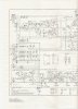
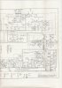
Ok, new attempt with the schematics, hope this works better. Download from Zippyshare:
First page:
https://www117.zippyshare.com/v/jwelQcCy/file.html
Second page:
https://www117.zippyshare.com/v/3OoG9fxg/file.html
...also realized I've totally missed to try swapping speakers L/R to rule out a speaker issue and also not tried the B-speaker connections. That may give more info in the troubleshooting
First page:
https://www117.zippyshare.com/v/jwelQcCy/file.html
Second page:
https://www117.zippyshare.com/v/3OoG9fxg/file.html
...also realized I've totally missed to try swapping speakers L/R to rule out a speaker issue and also not tried the B-speaker connections. That may give more info in the troubleshooting
It looks like a pretty simple, straight forward topology. Since the problem is in one channel and independent of the pre-amp we can rule out the preamp and power supply. My first guess would be the 2200uF output cap. Those can get noisy when they go south. If it were a diode I'd think it would be most noisy when on and warm, not at power on and off. Same with resistors. My old Marantz 2230 got noisy output caps. Cheap and easy fix and probably worth replacing anyways if they're old.
T68
Super Member
It looks like a pretty simple, straight forward topology. Since the problem is in one channel and independent of the pre-amp we can rule out the preamp and power supply. My first guess would be the 2200uF output cap. Those can get noisy when they go south. If it were a diode I'd think it would be most noisy when on and warm, not at power on and off. Same with resistors. My old Marantz 2230 got noisy output caps. Cheap and easy fix and probably worth replacing anyways if they're old.
Thanks ReactiveLoad! Yup, I´ll think that´ll be my first course of action. Got a new multimeter with capacitance measure incoming. Could this kind of trouble be measuered so I can see if the output caps are bad?
If I don´t find the exact 2200uf capacitance. How critical is it if I use caps with other parameter?
They're not that critical a value. You don't want to go lower because that rolls off the bass at a higher point, and you don't want to go much bigger because that increases the power-on thump you can get. Higher voltage is always better. Paralleling is perfectly acceptable to get the value you want, like a 2000uF and a 330uF in parallel.
It's unlikely a DMM cap test will check leakage, but if their much over their rated capacitance, that's a good sign their dying.
It's unlikely a DMM cap test will check leakage, but if their much over their rated capacitance, that's a good sign their dying.
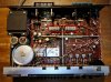
There is plenty of room to install 2200uf radial caps standing up. Just measure from the board and the top of the case to be sure not to get too tall of ones. If it were me, I would be replacing all of the Gray Elna Bombs since they are way past their life expectancy. Using radial caps instead of axial are just fine as long as there is room, and I don't see any in the photo that would have a problem fitting radial leaded caps. They don't "have" to sit flat on the board to work properly.Yep. That's them. Unfortunately axials like those aren't too easy to come by these days. Not sure what I'd replace them with.
 Plus if I need to extend any leads, I always extend the negative lead, keeping the positive lead as short as possible to help prevent any possible "noise" issues.
There is plenty of room to install 2200uf radial caps standing up. Just measure from the board and the top of the case to be sure not to get too tall of ones. If it were me, I would be replacing all of the Gray Elna Bombs since they are way past their life expectancy. Using radial caps instead of axial are just fine as long as there is room, and I don't see any in the photo that would have a problem fitting radial leaded caps. They don't "have" to sit flat on the board to work properly.
That's probably what I'd do too. Glad you pitched in.
T68
Super Member
Did a quick search at Elektrokit (swedish vendor for components) and had no problems finding axials at right spec for the filters.
While I was at it I looked for powercaps but here there were none at right specs. Maybe the standards have changed since then?
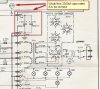
The schem has them at 3000 uF / 70v. The closest I can find is 3300 uF/63V. I see at the schem there seems to be 63V at the caps. So maybe thos will do? Thanks in advance for further advice!
While I was at it I looked for powercaps but here there were none at right specs. Maybe the standards have changed since then?
The schem has them at 3000 uF / 70v. The closest I can find is 3300 uF/63V. I see at the schem there seems to be 63V at the caps. So maybe thos will do? Thanks in advance for further advice!
Never go lower in voltage. You always want to be about 20% above the expected operating voltage to give a cushion against voltage spikes and fluctuations. 3300uf/80v, or 100v will be fine. Although you may find 71v somewhere, I would still use no less than the 80v if it were me.Did a quick search at Elektrokit (swedish vendor for components) and had no problems finding axials at right spec for the filters.
While I was at it I looked for powercaps but here there were none at right specs. Maybe the standards have changed since then?
The schem has them at 3000 uF / 70v. The closest I can find is 3300 uF/63V. I see at the schem there seems to be 63V at the caps. So maybe thos will do? Thanks in advance for further advice!
View attachment 1691986
View attachment 1691986

No! The supply voltage already is 63 volts and that would eat all your margin! Get 100 V units, 80 V almost don't exist. These 100 V units will prolly be smaller too than the ones in your unit. Also note that you usually can use larger values than in the schematic so you can get quantum discounts. Like only use 100 µF units if the schematic also calls for 47 or 68 µF caps.
Edit: there are many caps of 100 and 220 µF of various voltages. Replace them all with 220 µF/25 V.
Attached the schematic joined together-
Tjerk, 9ZZ
Edit: there are many caps of 100 and 220 µF of various voltages. Replace them all with 220 µF/25 V.
Attached the schematic joined together-
Tjerk, 9ZZ
Attachments
Last edited:
