• The move to the new server is done. There are some software and database maintenance updates in process. This has us passing the hat around to help out. We appreciate any donations. Seriously, even a dollar helps. The payment page may be found here - https://www.audiokarma.org/support.html

Rectilinear III crossovers

Heck man, I'd just mark the wires well, take lots of photos and pull that pot (or L-pad). Then I'd spray the livin' crap out of it with some deoxit and let it sit a while. If it doesn't loosen up and turn, I'd bend the tabs back and open it up. Nothing to lose. Worst case scenario, try some DW40 then clean it up really, REALLY well and lubricate it before putting it back together. The phenolic board inside might swell if you don't get it cleaned up. I bet you can get it going again.

I agree with most of that since it is currently stuck in place.
I'm not familiar with DW 40. Is that a real product, a typo, or a joke?
I know some people don't recommend WD 40 as it can get gunky/dirty over time.
 
Last edited:
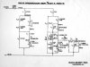
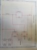
Thanks for providing the schematic - - - it's a really good sketch, but I'm unable to understand that type of circuitry. I can't even figure out which x-o components are associated with which drivers. :crazy:

I find it easiest to go back to fundamentals: inductors are low-pass devices, caps are high-pass. Start at the input and when you get to the first component, mentally split the signal there depending on the component. Then move on to the next. You can even take 2 or 3 high lighters to represent bass, mid (if present) and treble. Start them each in separate lines at the input, and draw out where that portion of the signal goes to get to its driver.

Once you see one of them work and it clicks in your head, it's kinda cool. Weird and gratuitously unnecessary, but cool.
 
I agree with most of that since it is currently stuck in place.
I'm not familiar with DW 40. Is that a real product, a typo, or a joke?
I know some people don't recommend WD 40 as it can get gunky/dirty over time.

My fingers sometimes won't obey my mind. That was a typo and supposed to be WD 40.
That product would be a last resort in my mind, to be tried just short of tossing the pot out. I'd only use it if the post was so seized up it won't move. Then I'd clean the ever-loving crap out of it to get all the WD 40 out, then fine sandpaper, then Deoxit.
 
My fingers sometimes won't obey my mind. That was a typo and supposed to be WD 40.
That product would be a last resort in my mind, to be tried just short of tossing the pot out. I'd only use it if the post was so seized up it won't move. Then I'd clean the ever-loving crap out of it to get all the WD 40 out, then fine sandpaper, then Deoxit.

I was kind of hoping it was a new (or unknown to me) product that might be helpful for various audio related issues.
Oh well. Typos happen.:)
 
Then I'd clean the ever-loving crap out of it to get all the WD 40 out, then fine sandpaper, then Deoxit.

That would require a lot of work. Not impossible but a lot of unsoldering and re-soldering.
And that would be just to get the pots out to where they could be opened up.
I couldn't tell from the OP's photos which crossover he has but here's a series one.
 

Attachments

  • later series crossover.jpg
    later series crossover.jpg
    90.2 KB · Views: 40
15836105399744784983422193173107.jpg
Thanks for providing the schematic - - - it's a really good sketch, but I'm unable to understand that type of circuitry. I can't even figure out which x-o components are associated with which drivers. :crazy:
 

Attachments

  • 15836107002938251342948739474574.jpg
    15836107002938251342948739474574.jpg
    34.3 KB · Views: 53
  • 1583610752825166678651311281508.jpg
    1583610752825166678651311281508.jpg
    64.2 KB · Views: 49
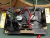
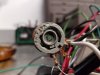
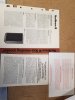
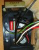
Thank you everyone for the help to this point. Here are some more pics. It appears as though this thing got super hot at some point. Tried a good dose of Fader lube on it but no dice. The schematic matchs up with what I have coils, caps and resistors. I am also have the original paper work that came with the speakers!
 
I have that schematic you posted but I naturally had to measure everything myself. My sketch matches the schematic and it has the coils' values.
Yeah good luck with the pots.
The paper work is very cool!
 
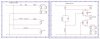
This is a very interesting thread - - look here what I found amid my messy files.. I know there was a Rect-III version earlier than either of these two - - - I think it had only one pot or maybe even none. The "XTC" cap noted here in the '69 version is the one I noted earlier as 90uF.

I do not own the Rect-III, but I do have some Rect Mini-III's and now I'm beginning to wonder how that crossover is wired.

Rectilinear III schematics - 69 and 71.jpg
 
As I said in post #16, the first few crossovers were parallel then they switched to series.
I have another of my hand drawn schematics for a Mini-III. I'll post it tomorrow. It is parallel.
That 90uF cap is probably supposed to be 80uF.
 
Oops! I had BIG III on my brain when I said 80uF. Sorry.

However, in my Rectilinear fever, I failed to notice that there are 2 different Mini III crossovers.
Oops again.
One is on a piece of masonite with a paper label facing the outside and the other has the black plastic plate.
The masonite one doesn't have the 8ohm 10W resistor, the coil is different and the tweeter capacitor is different.
I think the masonite one is the early variety because it is simpler and low cost. My serial #'s are in the 14xxx range.
All 3 of mine are that early variety.

Can't post a schematic for you since mine is different. I'm looking at the available pictures of what I call the "B" type later crossover. If I could get some more pictures I'd be more confident.
I don't want to give you a "guesstimated" schematic.
 
Last edited:
I failed to notice that there are 2 different Mini III crossovers.
I wasn't aware of this either, but I suppose the evolution of the Mini-III had some parallels to the evolution of the larger Rect-III. I have never been able to find any version of schematic for the Mini-III, so I just might have to try to sketch one up myself someday.
 
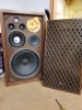
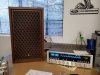
I just picked these Sansui SP -2000's up on Offer Up this past weekend for $100 bones! Ten minutes from my house. At least I have something while I work on the III's! It appears all the drivers work on this set. Maybe a recap in their future also. Put up a couple pics with my 4300 that another AK member recaped for me. This new hobby is getting expensive haha!
 

Attachments

  • 1583800614689524317858840060291.jpg
    1583800614689524317858840060291.jpg
    74.9 KB · Views: 18
  • 15838006944917929788188272379023.jpg
    15838006944917929788188272379023.jpg
    114.8 KB · Views: 16
/rant on/
I would love Jon Dahlquist to actually explain what is going on with the DQ-10 crossover.
Yeah, I know they sound great but that crossover eats watts.:eek:
The other thing is the same woofer in an OLA isn't lacking bass so where did that go in a DQ-10?
/rant over/

I bought DQ-10 s last year and recently removed the woofers to find that the box has partitions
on either side of the woofer with a slot opening to the rest of the box providing 3 chambers.
This is very similar to the Dyna A-35 and A-50 sealed 2 chamber "aperiodic" designs.
He probably did this to lower the Qtc of the system but doing that also attenuates the deep bass
output. The box volume has been reported on here as 1.2 cu ft which causes a higher Fc than
in the 1.7 cu ft Large Advent also reducing bass extension.
For the DQ-10 being such a complex speaker you'd think he would have matched the bass of
the LA.
 
the box has partitions
on either side of the woofer with a slot opening to the rest of the box providing 3 chambers

Interesting but I don't understand. If it is divided into. say thirds, then how can just 1 slot connect them all together?
A sketch might be in order.

I always thought the DQ-10 woofer enclosure was more or less an OLA on its side. Wrong again apparently.
 
Interesting but I don't understand. If it is divided into. say thirds, then how can just 1 slot connect them all together?
A sketch might be in order.

I always thought the DQ-10 woofer enclosure was more or less an OLA on its side. Wrong again apparently.

There are boards running top to bottom on the right and left of the woofer
that run to the back of the box but each ends about 1" away from the back
forming a slot to each side cavity. The woofer is off center so they are not the
same size.
 
Last edited:
Back
Top Bottom