• The move to the new server is done. There are some software and database maintenance updates in process. This has us passing the hat around to help out. We appreciate any donations. Seriously, even a dollar helps. The payment page may be found here - https://www.audiokarma.org/support.html

Regulated DC Filament Supply (Pete Millet)

John Berard

AK Subscriber
Subscriber
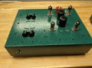
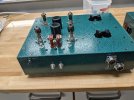
I am in the initial stages of planning a new 2A3/6SL7 amplifier build. This will be my 2nd build and I am going through the ins-and-outs of learning. The number one realization is that almost everything has it's trade-offs. I am exploring going all SS regulated power and have been doing some experimentation. It is my understanding that with DC filaments, there is no need for hum pots and elevating the grounds. Please feel free to correct me if I am wrong as any input is much appreciated. To keep things neat and compact, I picked up a few of Pete Millet's filament DC power pcbs, built them and putting them to the test.

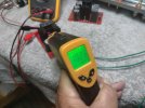
The filament boards were easy to build and work flawlessly. One needs to consider input voltage overhead to take advantage of the voltage regulation. For 6.3v consider 7-7.5v input. For 5v, a 6.3v tap is perfect. For 2.5v, both 5v and 6.3v work great. There is very good range using all the values in the BOM. At 6.3v, the ranges is 2.4v-5.5v. At 7.0v, the range is 2.42v-6.4v. Obviously, the tradeoff is heat dissapation. Testing using one EL34, 6.3v 1.5A, I read around 102F. This doesn't seem like much until you consider having four regulators. One of each of the 2.5v 2A3s, one for the two 6.3v 6SL7s and one for the B+.

Okay, I know many are purists and believe that SS doesn't belong in tube amps and everything must be point to point. My first build was an EL34 Skunkie Design without any SS and I enjoyed it greatly. But I am also an experimenter and like things that are often different. Sometimes to a fault. :p

And after all this, I am asking myself; why not just regulate the AC on the primary side of the PS transformer or use an external regulated power conditioner/regenerator? Ramifications?

Looking forward to all the comments.

IMG20251025090018.jpg

IMG20251025090422.jpg
 
Last edited:
Register to hide this ad
Might still need to elevate the filament supply. Depends on the circuit. If you have a driver tube for instance that has a high cathode voltage you need to be aware of the max heater to cathode specs in the data sheets. Elevating the filament supply is a way to control this issue. This can happen with a cathodyne phase splitter or sometimes a long tail pair or an SRPP type driver circuit. Depends on the tubes used and the circuit voltages.
 
Might still need to elevate the filament supply. Depends on the circuit. If you have a driver tube for instance that has a high cathode voltage you need to be aware of the max heater to cathode specs in the data sheets. Elevating the filament supply is a way to control this issue. This can happen with a cathodyne phase splitter or sometimes a long tail pair or an SRPP type driver circuit. Depends on the tubes used and the circuit voltages.
Yup, this SRPP 6SL7 driver still needs the heater elevated to 80ish volts. Also you are gonna find regulating down to 2.5V is gonna create more heat.
 
An indirectly heated tube will not benefit from DC on the heaters unless it is maybe in a microphone or phono stage.

As you discovered, heat dissipation has to be heeded. Depending on the regulator type (LDO - low drop out [1085] or normal such as a 317), this will dictate the input voltage that can be used and still keep dissipation to a minimum. Current draw will also have an impact on minimum voltage overhead needed.
 
Yup, this SRPP 6SL7 driver still needs the heater elevated to 80ish volts. Also you are gonna find regulating down to 2.5V is gonna create more heat.
A larger heat sink will most likely be needed.
I built Tubelab's first version of the 300B amp. It uses a 5V, 5A dual regulator. So it runs at the ragged edge. It needed a rather large heat sink to keep it cooler so it wouldn't shut down.
 
And after all this, I am asking myself; why not just regulate the AC on the primary side of the PS transformer or use an external regulated power conditioner/regenerator? Ramifications?
Stay away from using the incoming AC directly without a transformer for safety isolation. You don't want to tangle with a shock directly from the line. Some old radios did this without a transformer but they had cases that were nonconducting to prevent shocks.
 
Many different voltages and currents can be realized with a three terminal regulator and pass transistor if you want higher currents.

I have a ton of TO-3 317K's so I use them when I can.

Here is an example :

317K Pass Transistor Filament Regulator_DIY_v2.1.png
 
Might still need to elevate the filament supply.
Yep. Learned something new. Thanks!
An indirectly heated tube will not benefit from DC on the heaters unless it is maybe in a microphone or phono stage.
As you discovered, heat dissipation has to be heeded.
My only thoughts about DC for the 6SL7 valves was just to keep AC away from the signal path. I may be over complicating this and not understanding how much heat dissapation will occur especially when I haven't even factored in the dual PS filter and cathode resistors. Maybe drop the DC to the input valves and go single rail PS or use two small secondary inductors on the dual rail. So much to weigh in. It's kinda fun.
Stay away from using the incoming AC directly without a transformer for safety isolation. You don't want to tangle with a shock directly from the line. Some old radios did this without a transformer but they had cases that were nonconducting to prevent shocks.
Duly noted.
Many different voltages and currents can be realized with a three terminal regulator and pass transistor if you want higher currents.
I have a ton of TO-3 317K's so I use them when I can.
Here is an example :
Thanks for sharing. Hopefully I will absort enough knowledge to someday impliment such a circuit. But right now, I admit it is too advanced for me.
 
My only thoughts about DC for the 6SL7 valves was just to keep AC away from the signal path. I may be over complicating this and not understanding how much heat dissapation will occur especially when I haven't even factored in the dual PS filter and cathode resistors. Maybe drop the DC to the input valves and go single rail PS or use two small secondary inductors on the dual rail. So much to weigh in. It's kinda fun.

Duly noted.

Thanks for sharing. Hopefully I will absort enough knowledge to someday impliment such a circuit. But right now, I admit it is too advanced for me.
The spiral wound heater does an excellent job of cancelling AC current as to not radiate an electromagnetic field. Indirectly heated tubes are inherently very quiet except where noted about sensitive microphone, phono or other very low level (<5mV signal) stages.
 
why not just regulate the AC on the primary side of the PS transformer or use an external regulated power conditioner/regenerator?
That can help, as this will keep the primary voltage constant, and if the load on the secondary has constant current draw (as in an SE amp) it will keep the secondary voltage constant, therefore regulated. The other benefit of primary side regulation is keeping the AC frequency constant. The power company (at least in my area) does a pretty good job of regulating both voltage and frequency, but it is not perfect and can spike or dip depending on overall community load. I used to use an early version of one of PS Audio's regulator/regenerator products, but overall I found it added a bit of an anemic quality to the sound, so these days I prefer to run on straight wall socket current with no regulation, and if I need regulation in the amp I'm building I will put that regulation on the secondary side.

For PP designs, regardless of whether or not the primary is regulated, there can be significant current draw differences between idle and full power of the output stage, which can pull down B+ at high power due to the internal resistance of the PT and the impedance of the rectification circuit. So it is often desired, if building an upper crust HiFi PP amp, to regulate all the voltages that are used to set the output stage's operating point. That includes the high voltage supply, the screen supply, and the bias supply. There are a half dozen ways to regulate--design a low impedance power supply and rectification circuit and avoid regulation, choke input regulation, shunt regulation, linear regulation, SMPS (switch-mode power supply) regulation, predrop style regulation (as in the Maida approach), and sliding-bias regulation (as in the EFB approach), to name several. The issue as you noted that I think is the Achilles heel of linear regulation is the heat dissipated in the regulator itself. It can be significant and needs to be dealt with properly.

Several top shelf commercial PP designs that I'm aware of that perform linear regulation are the Conrad Johnson line of products (from the 80's and 90's)--they used transistor-based regulation, and the Audio Research line of products from the 70's and 80's-- they used tube-based regulation.
 
Last edited:
The simple approach is two center-tapped 2.5v filament windings of the proper current rating, each one wired to its own 2A3.
Then wire the filament/cathode resistor and bypass cap to ground from the center-tap.

With decent layout, it should be rather quiet even without a hum pot. Unless the tubes are way off with respect to emission.
But I can understand wanting to experiment...

The Millet PCBs would be nice for heating a 300B, or 71A. Or regulation for a line-stage/preamplifier.
 
ofc you get the endless debate about the sound of AC vs DC filaments in a DHT. There is actually some technical reasoning behind why it probably does sound different. How different, no idea, I don't fool with those. Everything about those is more expensive and more fussy than I have any desire to mess with.
 
ofc you get the endless debate about the sound of AC vs DC filaments in a DHT. There is actually some technical reasoning behind why it probably does sound different. How different, no idea, I don't fool with those. Everything about those is more expensive and more fussy than I have any desire to mess with.
I've learned my best tricks resolving fussy electronic problems... either design or repair related. It can definitely consume a vast amount of time, but it keeps my brain active. My wife asked me once how come I was not tinkering as much as I use to and I said I was thinking about a problem I am having. She said well how are you going to solve it if you are not down there tinkering? I said "I'm thinking about it" and she just looked at me.
 
That can help, as this will keep the primary voltage constant, and if the load on the secondary has constant current draw (as in an SE amp) it will keep the secondary voltage constant, therefore regulated. The other benefit of primary side regulation is keeping the AC frequency constant. The power company (at least in my area) does a pretty good job of regulating both voltage and frequency, but it is not perfect and can spike or dip depending on overall community load.
I have measured my mains and they can vary +/- 5 volts depending on the season. With summer here in florida, the a/c, pool pumps and fridge have a major impact. Then add all my neighbors doing the same thing. :oops:
Everything about those is more expensive and more fussy than I have any desire to mess with.
Yes, but compared to what I am spending on all ISO Tango iron, the cost is small.
I've learned my best tricks resolving fussy electronic problems... either design or repair related. It can definitely consume a vast amount of time, but it keeps my brain active.
Yes! I am retired but never bored. Much better than spending time in a chair waiting for one's end.
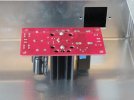
I use the same regulators often. here is one way I keep the cool.
Neat solution you did. I am considering mounting the heat sinks directly to the inside top or side of the the chassis. The chassis would then be a coupled heat sink and only two holes needed for mounting instead of the 4 on the pcb.


IMG20251026131709.jpg
 
I've learned my best tricks resolving fussy electronic problems... either design or repair related. It can definitely consume a vast amount of time, but it keeps my brain active. My wife asked me once how come I was not tinkering as much as I use to and I said I was thinking about a problem I am having. She said well how are you going to solve it if you are not down there tinkering? I said "I'm thinking about it" and she just looked at me.
I figure the people that designed vacuum tubes solved the problem with indirect heat, and I'm not smarter than they were so I'll use their solution.
 
I have measured my mains and they can vary +/- 5 volts depending on the season. With summer here in florida, the a/c, pool pumps and fridge have a major impact. Then add all my neighbors doing the same thing. :oops:

Yes, but compared to what I am spending on all ISO Tango iron, the cost is small.

Yes! I am retired but never bored. Much better than spending time in a chair waiting for one's end.

Neat solution you did. I am considering mounting the heat sinks directly to the inside top or side of the the chassis. The chassis would then be a coupled heat sink and only two holes needed for mounting instead of the 4 on the pcb.


View attachment 3621905
Cool idea! That's how PM suggests mounting his new CCS units.
 
I use the same regulators often. here is one way I keep the cool.
View attachment 3621826View attachment 3621827
I have a preamp with voltage regulated heaters and B+ using the same type heat sinks. I used a taller version for the 300B heater regulators and mounted the heat sink flat against the underside of the chassis. It keeps the dual regulator at around 95°F.
 

Attachments

  • 20240305_152555.jpg
    20240305_152555.jpg
    123.5 KB · Views: 27
Yup, this SRPP 6SL7 driver still needs the heater elevated to 80ish volts. Also you are gonna find regulating down to 2.5V is gonna create more heat.
Is there a formula for this? If I were to do a 6b4g/6sl7 running a B+ of 300v, still -81v elevated or would it be a certain percentage of B+? Your 2a3/6sl7 running with a B+ of 355v works out to 23% at -81v elevation.
 
I think it mostly depends on the cathode voltage at the "upper" triode in the SRPP setup. I want to say the normal config is to basically divide the B+ in half, so the upper cathode would be ballpark 150v. +80v is not unreasonable given that. H-K at the upper tube will be about +70 and at the lower section it'll be around -75. H-K limit for most tubes is 100 volts +/- so that would have it in spec.
 
Back
Top Bottom