• The move to the new server is done. There are some software and database maintenance updates in process. This has us passing the hat around to help out. We appreciate any donations. Seriously, even a dollar helps. The payment page may be found here - https://www.audiokarma.org/support.html

Regulated DC Filament Supply (Pete Millet)

Is there a formula for this? If I were to do a 6b4g/6sl7 running a B+ of 300v, still -81v elevated or would it be a certain percentage of B+? Your 2a3/6sl7 running with a B+ of 355v works out to 23% at -81v elevation.
The 6SL7GT spec for heater elevation is + 90V relative to the cathode. If your upper cathode is sitting at 150VDC, then you have a window of 240VDC~60VDC that the heater can be elevated to. In SRPP for a 6SL7, I usually run it at around 100VDC, which makes it -50VDC in spec terms.
 
A comment was made in an earlier post about regulating down to 2.5VDC and the heat (power dissipation) it would create... it is not the fact that you are regulating to 2.5VDC but the fact that you are going down to 2.5VDC from a much higher unregulated voltage. Voltage difference across the regulator (input V versus output voltage) causes heat dissipation. If you keep your input voltage a few volts above the output voltage plus the drop-out voltage, you will have minimal heat dissipation and a cooler operating regulator. Just FYI.
 
On my 6SL7 SRPP 2A3, one cathode is at 2V and the other is at 165V so I lift the heater to ~83V to split the difference. That keeps both the upper and lower cathode safely away from the limit on the datasheet.
 
A comment was made in an earlier post about regulating down to 2.5VDC and the heat (power dissipation) it would create... it is not the fact that you are regulating to 2.5VDC but the fact that you are going down to 2.5VDC from a much higher unregulated voltage. Voltage difference across the regulator (input V versus output voltage) causes heat dissipation. If you keep your input voltage a few volts above the output voltage plus the drop-out voltage, you will have minimal heat dissipation and a cooler operating regulator. Just FYI.
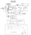
This is now what I have come up with. Using a single 5V 10A transformer for both the 2A3 filament DC supply modules.

2A3-PSU 5U4G Dual Rail.jpg
 
Each regulator prefers to have its own 5VAC winding. A long time ago I was experimenting and discovered using one winding caused noises issues that could not be resolved. In addition, the bias voltage will back-feed across/thru the regulators back to the AC winding.
 
Each regulator prefers to have its own 5VAC winding. A long time ago I was experimenting and discovered using one winding caused noises issues that could not be resolved. In addition, the bias voltage will back-feed across/thru the regulators back to the AC winding.
Thanks for your input. Is the back-feed issue in all cases or just when two regulators are powered by a single winding?
 
I know many are purists and believe that SS doesn't belong in tube amps and everything must be point to point.
The point to point thing is nice if you do changes to the circuit after the fact. You can control stray capacitance pretty well (usually a board is better) but you had better not make a rat's nest out of it for that to be the case :)

I would not worry about using solid state to regulate the filament. However, in your schematic:
This is now what I have come up with. Using a single 5V 10A transformer for both the 2A3 filament DC supply modules.

View attachment 3666024
The B+ is getting a double whammy as AC line Voltage changes. As it does so not only does the high Voltage change but so does the filament supply for the rectifier. So this makes the circuit more prone to AC line Voltage problems as it will result in greater variation of the B+.

If you are making a hifi amp as opposed to a guitar amp, there's really not a good argument for the tube rectifier unless the B+ will be too high for the intended circuit using solid state. The trick is to make sure the solid state rectifiers are properly silenced, which is really more a matter of silencing the power transformer when the rectifiers are installed. To this end you need to keep the transformer leads as short as possible. To silence the circuit the best means is a resistor and capacitor in series, placed across the input to the rectifiers. Usually a 0,01uf cap is a good place to start. A variable resistance can be placed in series with that cap and the ideal value dialed in.

Tube rectifiers look cool but unless that's the reason for using them or the B+ will be too high otherwise their day has come and gone.

 
The B+ is getting a double whammy as AC line Voltage changes. As it does so not only does the high Voltage change but so does the filament supply for the rectifier. So this makes the circuit more prone to AC line Voltage problems as it will result in greater variation of the B+.

If you are making a hifi amp as opposed to a guitar amp, there's really not a good argument for the tube rectifier unless the B+ will be too high for the intended circuit using solid state. The trick is to make sure the solid state rectifiers are properly silenced, which is really more a matter of silencing the power transformer when the rectifiers are installed. To this end you need to keep the transformer leads as short as possible. To silence the circuit the best means is a resistor and capacitor in series, placed across the input to the rectifiers. Usually a 0,01uf cap is a good place to start. A variable resistance can be placed in series with that cap and the ideal value dialed in.

Tube rectifiers look cool but unless that's the reason for using them or the B+ will be too high otherwise their day has come and gone.
In properly designed equipment, this is a moot point. Gazillions of tube type equipment have been produced and are still around being restored.

Tube rectifiers are still very much alive, and people use them every day in new builds.
 
The point to point thing is nice if you do changes to the circuit after the fact. You can control stray capacitance pretty well (usually a board is better) but you had better not make a rat's nest out of it for that to be the case :)

I would not worry about using solid state to regulate the filament. However, in your schematic:

The B+ is getting a double whammy as AC line Voltage changes. As it does so not only does the high Voltage change but so does the filament supply for the rectifier. So this makes the circuit more prone to AC line Voltage problems as it will result in greater variation of the B+.

If you are making a hifi amp as opposed to a guitar amp, there's really not a good argument for the tube rectifier unless the B+ will be too high for the intended circuit using solid state. The trick is to make sure the solid state rectifiers are properly silenced, which is really more a matter of silencing the power transformer when the rectifiers are installed. To this end you need to keep the transformer leads as short as possible. To silence the circuit the best means is a resistor and capacitor in series, placed across the input to the rectifiers. Usually a 0,01uf cap is a good place to start. A variable resistance can be placed in series with that cap and the ideal value dialed in.

Tube rectifiers look cool but unless that's the reason for using them or the B+ will be too high otherwise their day has come and gone.
There are more benefits to point-to-point than that. Ease of repair. I recently had some resistors fry on the input pcb of my Dynaco ST70. The board was totally fried and needed to be replaced along with all the mounted components. Took a fair amount of time and money to fix. If it had been fully point-to-point, it would have been a simple diagnosis and fix for $2 worth of resistors.

Simplicity is king. If I have a tube rectifier go bad, I open up the drawer, grab a replacement and pop it in. Five minutes max. I have only replaced one in the last ten years. I also don't need to be an electronics engineer to do so but understand the slow start benefits of my GZ32/5AR4 rectifier. :)

I think we would agree that proper design is essential no matter if it is old or new school. Bad designs exist in both, including poorly laid out pcbs that have ac traces running parallel to dc traces, underrated traces, etc. I coexist with both. But I am old enough to have learned, old technology may not be efficient, but in most cases it is more user friendly. Heck, I can fix my '67 gas guzzling, carbureted Vette with nothing more than a screw driver, pair of pliers and a hammer in most cases.
 
Two regulators powered by single winding for DHT filament use. Other application not an issue.
Bear with me a bit longer Nick. Due to constrained chassis real estate space, I have been looking for a single transformer with dual secondary windings. Lots of 6.3v but next to none in 5V with appropriate amp load. Could a 10V CT 20A work using half for each module? Or would that common leg (CT) still be considered a single winding? I am looking at this one HERE. I dunno.
 
Bear with me a bit longer Nick. Due to constrained chassis real estate space, I have been looking for a single transformer with dual secondary windings. Lots of 6.3v but next to none in 5V with appropriate amp load. Could a 10V CT 20A work using half for each module? Or would that common leg (CT) still be considered a single winding? I am looking at this one HERE. I dunno.
Yep. Not many 5VAC candidates out there and they would be perfect for regulating down to 2.5VDC. The 266PA12 is a bit overkill, but as a general rule, I use a transformer that has at least double the needed DC current.

e.g. - If a filament needs 2.5 amps, use a transformer rated at 5 amps or greater.
 
Yep. Not many 5VAC candidates out there and they would be perfect for regulating down to 2.5VDC. The 266PA12 is a bit overkill, but as a general rule, I use a transformer that has at least double the needed DC current.

e.g. - If a filament needs 2.5 amps, use a transformer rated at 5 amps or greater.
Pete recommends 4A as a bare minimum for a 2A3 so your 2X A makes perfect sense.

Well, I have learned a bunch about inserting SS DC regulated filament supplies and required windings. In general, 1) one would need a transformer rated at +1.5-2V over to cover the voltage drop of the required filament voltage, 2) Each DC regulated supply must be on it's own PT winding, 3) PT should be rated at 1.8X or more current of filament specification.

If I got this right and want to keep dissipation at a minimum, a 2.5V 2.5A 2A3 filament would ideally have a PT that is 4.5V 5A.

The Hammond 266PA12 is overkill as you mentioned but would also produce more heat being 6V regulated down to 2.5V. Nobody seems to have these in stock here in the USA and the wait time is up to month. I am now considering just having a custom wound PT done by Edcor or Hayboer. If I have to wait, why not get a PT with ideal specs. for the application?
 
The extra volt will cause additional dissipation, however, for a "built-in" heat sink you can use the aluminum enclosure chassis or top plate. With all the surface area, the chassis or top plate will barely get warm. I have done this many times with no issues.

Don't get too hung up on dissipation, as long as the heat sink can pull the heat away and keep (the semiconductor) temperatures manageable, that is the most important aspect.
 
Last edited:
Hawk Electronics has them. Lowests prices on all Hammond stock:
Hawk had me a bit confused because of the 'drop ship' info that had me believing it would come direct from Hammond. Either way, I placed an order with them. I have ordered Hammond transformers from them in the past and they do have the lowest prices.

The extra volt will cause additional dissipation, however, for a "built-in" heat sink you can use the aluminum enclosure chassis or top plate. With all the surface area, the chassis or top plate will barely get warm. I have done this many times with no issues.

Don't get too hung up on dissipation, as long as the heat sink can pull the heat away and keep (the semiconductor) temperatures manageable, that is the most important aspect.
Yes, did that. I was also going to use taller heat sinks but space didn't allow. I did also mount the trim pot on the bottom of the pcb for easy access.

P Millet Mounted.jpg
 
Last edited:
Maybe a redundant question, but do you have heat sink compound between the black heat sink on the module and the aluminum chassis? There is not a lot of surface "mating" area there so heat transfer may not be optimal from the black heat sink to chassis, but it probably is.
 
Maybe a redundant question, but do you have heat sink compound between the black heat sink on the module and the aluminum chassis? There is not a lot of surface "mating" area there so heat transfer may not be optimal from the black heat sink to chassis, but it probably is.
Not yet because I am just mocking up at this point. But thermal compound will be used at final assembly.
 
Back
Top Bottom