• The move to the new server is done. There are some software and database maintenance updates in process. This has us passing the hat around to help out. We appreciate any donations. Seriously, even a dollar helps. The payment page may be found here - https://www.audiokarma.org/support.html

Replacing Klipsch Midrange Diaphragms wi

The horn itself has 3 order rolloff, so only a first Order capacitor is-
required to work in concert with that. You can just blend the tweeter with the natural midrange rolloff. When I had my 3 &way, setup with my Quarter Pie bass horns, the K402/K1133 with a b&c DE-250 were crossed at 400 and 4,000 Hz. respectively with only a Single Capacitor on each of the midrange and tweeter Drivers. It sounded fantastic, as all pure horn systems do!
Free advice is worthless, even from me. You pays your money and you takes your chances. Get REW and a microphone. Everyone has a laptop, so measure and do it accordingly. Ignore all the opinions and get it MEASURED.
 
Alright; old thread, dumb question. Isnt it possible to bring the crossover point of the Ti mid down to 6k by changing the value of the caps/coils in the mid circuit? thereby eliminating the need for more components in the circuit?
There are no caps/coils in the original networks to change.. They used the natural rolloff of the phenolic diaphragm and the horn to limit upper frequency extension. The Ti diaphragm rolloff is 1,000hz higher. Bob’s bandpass (which is identical to the ones Klipsch used in pro networks with the k52/k701) is needed to reduce tweeter overlap. Other option is to modify the tweeter network
 
Last edited:
There are no caps/coils in the original networks to change.. They used the natural rolloff of the phenolic diaphragm and the horn to limit upper frequency extension. The Ti diaphragm rolloff is 1,000hz higher. Bob’s bandpass (which is identical to the ones Klipsch used in pro networks with the k52/k701) is needed to reduce tweeter overlap. Other option is to modify the tweeter network

Did those pro networks also have the 4mh inductor across the autoformer?
 
I don’t recall there being one in the KP-361 that I parted out last fall. I do still have the t7a auto former, though and a few of the other crossover parts, mainly coil inductors
Kp362 didn’t have a k52 driver and used a tractrix mid horn. No bandpass. Crossed at 7,000hz
 
I do question the need for the 4mh inductor. The specs for the T7A show an inductance of 4mh between the output taps. The inductor would cut that in half. 2mh is a pretty small value for a second order high pass. I've never been able to find the specs for the T9A, so it's inductance in parallel with the 4mh is a mystery. Regardless, that inductor has nothing to do with the 6khz low pass needed to tame the extended response of the Ti diaphragm.
 
Thx guys! Crites doesnt sell the bandpass anymore. Anyone have a schematic? I am working from the ALK design btw, not the original circuit.
 
Another newb question; why are there NP electrolytics used in both Crites and ALK networks? Is it just cost savings, or is there a reason to use them?
 
I do question the need for the 4mh inductor. The specs for the T7A show an inductance of 4mh between the output taps. The inductor would cut that in half. 2mh is a pretty small value for a second order high pass. I've never been able to find the specs for the T9A, so it's inductance in parallel with the 4mh is a mystery. Regardless, that inductor has nothing to do with the 6khz low pass needed to tame the extended response of the Ti diaphragm.
I’d bet the inductance of the T9A with a paralleled 4mh in the kp250 is pretty damn close to that of just the 3504 used in the Heresy II..

Sounds like Bob may have gotten these wrong…
 
Another newb question; why are there NP electrolytics used in both Crites and ALK networks? Is it just cost savings, or is there a reason to use them?
Doesn’t look like an electrolytic in the pics in Bob’s network. It’s not electrolytic in my kp250. It’s only a 1.5uf cap.
 
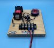
Here is a pic of the Crites board. The two caps that are piggybacked have rings around them, and are marked “NP”. Arent these non polarized electrolytics??
 
Would the bandpass work in an alk circuit, or is that apples and oranges?
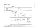
If you are referring to the ALK Universal, it already has a band pass. Al liked to put the squawker low pass before the autoformer. He used a 300uh/2.2uf lowpass based on 8 ohms. Bob's lowpass is meant to be placed after the autoformer and before the squawker. Since the load is basically doubled (14-15 ohms), the inductor needs to be doubled and the capacitor needs to be halved. The values Bob chose were close enough.
 
Thx. I was referring to the ALK circuit specifically built for forte 2. I was told the ALK uni was not a good fit for forte 2.
 
Back
Top Bottom