• The move to the new server is done. There are some software and database maintenance updates in process. This has us passing the hat around to help out. We appreciate any donations. Seriously, even a dollar helps. The payment page may be found here - https://www.audiokarma.org/support.html

Replacing The STV-3H and -4H Diodes

SV-02 and SV-03

I was able to locate some SV-03 biasing diodes from Consolidated Electronics. I believe they are pretty similar to STV-3H.

I am looking for some SV-02 replacements and haven't been able to find any. This thread shows that I can make a replacement for the SV-02 out of a couple of single diodes. While that is certainly a viable option I was wondering about the some other replacements. Using the NTE cross reference search, it shows that the following NTE devices are recommended -

NTE137A (1.2 VF Zener Diode)
and
NTE116 (General Purpose Diode with a 093v to 1.1v forward voltage)

The SV-02 datasheet says that it has a forward voltage range of 1.2V (1 mA) and 1.5V (70mA).

The NTE116 datasheet says that it has a typical forward voltage of 0.93V and a maximum of 1.1V. The test conditions were 1A forward current at +25 degree C.

The NTE137A Zener has a max forward voltage of 1.2V (200 MA).

What do you think about those?

Thanks,
Sonavor
 
This thread just saved me a whole load of headaches. I have a Spec 2 that I'm going to be rebuilding soon, the STV-4H diodes were replaced with some diodes mashed in a cardboard sandwich. I can see where the heat has "smoked" the cardboard. It's a situation that I'd like to remedy ASAP.
 
stv4h now available

I stumbled on this thread when I was restoring my Pioneer M-22 amp. Of course I broke the lead on one of two stv4h varistors used in the M-22. When I googled this part number I found there was nothing available and came upon this thread which was a great help. I did try to fix the broken lead by grinding out a clearance and resoldering the lead but did not feel good about the result. Hopefully this post can help someone else in the same position. I recently googled stv4h again and found that Pioneer electronics usa came up as a vendor. To my surprise the site showed a replacement item in stock (stv4hg) and I placed an order for 2. The price was high, 17 bucks apiece, as well as the minimum shipping charge of 15 bucks, but I bought them anyway, and they did indeed arrive a couple days later. They are just like the original piece except for the number stamp and the color of the polarity dot. I have not yet installed and tested them but expect to shortly and will follow up with a report.
 
The above is a vbe mulitplier circuit and are certainly used for bias compensation/stability and thermal tracking.
 
Echo Dude,
Thanks so very much for sharing your engineering research with all of us. These bias diodes have been a thorn in my side since around 1974.
I had difficulties even then buying them in small quantities.

I did a lot of service work for the solders at Ft. Monmouth, which was just down the street from our store. I always felt bad if one of them relocated or went TDY while their amp or receiver was sitting on my shelf waiting for parts, especially if it was one of these diodes. Worse yet was when the only part needed was one of these because I broke a lead off (I was only 14 and always in a hurry).
 
$49 is a ton of money for two diodes, but if I still had my M-22 I would most certainly buy them as well.

I stumbled on this thread when I was restoring my Pioneer M-22 amp. Of course I broke the lead on one of two stv4h varistors used in the M-22. When I googled this part number I found there was nothing available and came upon this thread which was a great help. I did try to fix the broken lead by grinding out a clearance and resoldering the lead but did not feel good about the result. Hopefully this post can help someone else in the same position. I recently googled stv4h again and found that Pioneer electronics usa came up as a vendor. To my surprise the site showed a replacement item in stock (stv4hg) and I placed an order for 2. The price was high, 17 bucks apiece, as well as the minimum shipping charge of 15 bucks, but I bought them anyway, and they did indeed arrive a couple days later. They are just like the original piece except for the number stamp and the color of the polarity dot. I have not yet installed and tested them but expect to shortly and will follow up with a report.
 
To revive a old thread, a solution from Sony for replacing SV04 Bias diodes. Might even work with ST4-series diodes.

Cheers,

The above is a vbe mulitplier circuit and are certainly used for bias compensation/stability and thermal tracking.
Indeed, but with no adjustment, and a wide range of needed voltages, that specific circuit is likely useful in precious few amplifiers.
 
what happens if this diode fails? My spec 2 will come out of protection once out of 100 and I know the STV4h is messed up. When it does come on the channel with the buggered diode puts out about 5 steady watts then spikes to 50 for a split second and its fine. The buggered stv4h measure real close to the other sides good one. BUT when the amp doesn't come out of protection it measures different. Does this make sense?

Something else wrong? I just had it serviced as it came back worse than it went in. They buggered the diode to begin with.
 
stv4h

That's what Iam talking about. Lots of work to help others is a trail to heaven. I remember people like this. best wishes, geo
 
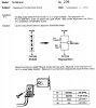
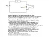
After reading a lot of threads here and exchanging some PMs with MarkTheFixer, I successfully tested some SVT-3H diodes from my Sansui G-6700 and some spares that I have scrounged from some parts units. I am pleased to say that all of them passed the test. Now I wan to share the step by step process that I went through:

Set up something with a breadboard or a terminal strip to ensure positive connections.
This is the circuit you will be building:

(see attached)

Measure the output of your battery source with your DMM.
Subtract 1.6V (the approximate drop across the STV-3H to be measured).
Divide this voltage by 0.00685 (7 mA is the current usually used by Pioneer and using a slightly smaller value adds a safety factor.)
Tack solder some resistors together in series and parallel to make a current limiting resistor of this value (RL).
Connect one side of RL to the positive (+) lead of the battery and the other side to the anode lead of the STV-3H. The cathode is marked with a yellow dot. Be very careful with the leads of the diode or you will likely break one off and be contacting Mark to get it fixed.
Connect the DMM leads across the leads of the diode, positive (+) to anode, and select the scale/range settings for ~5VDC.
Momentarily connect the negative (-) DMM lead and read the DMM.
A good diode should read in the range of 1.5 to 1.8V.
If you are reading ~ the value of your battery, you need to reverse the leads of the diode.
If it reads 0.000V the diode may be shorted.
If it reads less than 50 mV the diode may be open.
 

Attachments

  • STV-3H test circuit-A.jpg
    STV-3H test circuit-A.jpg
    110.9 KB · Views: 128
Last edited:
If you have a DMM with a diode range you can use that to test them if the meter puts out high enough voltage. If you have a second meter you can measure the voltage on the diode testing meter leads. If it's 2V or more you can test STVs with it.
 
Back
Top Bottom