• The move to the new server is done. There are some software and database maintenance updates in process. This has us passing the hat around to help out. We appreciate any donations. Seriously, even a dollar helps. The payment page may be found here - https://www.audiokarma.org/support.html

Replacing The STV-3H and -4H Diodes

So, if I understand this correctly, connecting three UF1004's in series is a suitable replacement for a single STV-3H varistor when used like so in this Pioneer SX-450 circuit:

STV-3H usage.png

If so, the three replacement diodes should be in series, like so:
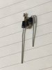
IMG_3121.JPG

and, if possible, embedded into a dollop of liquid steel on top of a heatsink / attachment point like the unfurled #4 ring terminal.
 
I made something similar, but the big leads on the 1004 diodes are so unwieldy that I clipped them off (leaving a couple of mm) and used clipped resistor leads to join the diodes. This allowed me to align the diode bodies nicely. And yes, I then used JB Weld to attach 'em to a ring terminal with the crimp end flattened out, more or less like I did with the 1N3595 diodes here.

But yes, you have the idea.
 
I made something similar, but the big leads on the 1004 diodes are so unwieldy that I clipped them off (leaving a couple of mm) and used clipped resistor leads to join the diodes. This allowed me to align the diode bodies nicely. And yes, I then used JB Weld to attach 'em to a ring terminal with the crimp end flattened out, more or less like I did with the 1N3595 diodes here.

But yes, you have the idea.
Excellent. Thanks!
 
Hoping the Sony SV04 replacement posted on the previous page by Findm-Keepm can be altered to replace an SV05 in a Sony?
 
Make it adjustable. Instead of the 1K fixed resistor between the base and emitter, make it a 1K trimpot, and add a 500 ohm resistor in series. Hopefully that'll give you enough range.
 
  • Like
Reactions: trs
Dunno what the voltage is supposed to be with the 2H. If it follows conventions, then a series'd pair of UF1004's should do it.
 
???
How are you planning to mount the proto board to the heat sink so that it can react to the thermal changes? You could probably cover all the diodes with JB Weld (molded with a flat object), drill the hole, and invert it to mount to the heat sink. This board may be too large to fit most places you'd find an STV-3H.
 
Now that's a good idea. I had one break a couple of weeks ago. Couldn't bear to toss it out so I still have it. Always good to have a spare.

- Pete
I'm really starting to hate this part (Toshiba SA-7100 receiver). The leads had broken off, so I carefully scraped them down and soldered new leads onto the stubs. Then, the stubs broke off. I found a couple of overpriced ones on ebay and bought them anyway; hopefully I can get at least one of them installed without breaking them again.
 
It would be easier to go with EW advice and use three UF1004s encased in JBWeld. Build a small "U" form laying on a flat surface, and line it with wax paper for easy removal. Make careful note of the anode and cathode, then trace a "+" and a "-" in the epoxy before it has hardened. I feel certain that you will remember, but this is a good legacy for the next person that works on it.
 
Since I need an STV-4H, would I use four of the UF1004 diodes, arranged anode to cathode in series, with the polarity etched in for reference, right?

I like the idea of the ring terminal for mounting it all.
 
Since I need an STV-4H, would I use four of the UF1004 diodes, arranged anode to cathode in series, with the polarity etched in for reference, right?
Yep.

Most Fluke meters have enough voltage available to forward bias four silicon diodes, so when I do these (infrequently) I don't bother with marking 'em, except for after the JB Weld sets. Then I put a dab of red fingernail polish on the cathode side.

Still haven't found a really satisfying replacement for the fat diode leads. In most applications, the diode is mounted some distance away from the solder points. I've been using lengths of solid copper wire stripped from some old Cat 5 cable, but I'd like to find something thinner and more flexible than that.
 
You wear red fingernail polish? :D

As for JBWeld, how is that to use? The last time I used any type of epoxy, it didn't end well. I had to glue together the upper clamp from a DVD player damaged in transit. I used some epoxy from Home Depot that was the kind that comes in the two tubes that you squeeze at the same time. It ran everywhere, glueing exactly the pieces together that I didn't want glued.

Lee.
 
You wear red fingernail polish? :D

As for JBWeld, how is that to use? The last time I used any type of epoxy, it didn't end well. I had to glue together the upper clamp from a DVD player damaged in transit. I used some epoxy from Home Depot that was the kind that comes in the two tubes that you squeeze at the same time. It ran everywhere, glueing exactly the pieces together that I didn't want glued.

Lee.

To stop this happening I use carefully placed pieces of sellotape to limit where it goes, although with some gluing jobs this is impossible. I agree the 2 part epoxy I am familiar with (Araldite standard) is surprisingly and annoyingly 'runny' after mixing.
 
Last edited:
Red, green, yellow, white . . . These days you can buy most any kind of polish at Alice's restaurant.

First you need to ensure that you use the prescribed amount of both parts of the epoxy - usually 1:1, but RTFM to make sure. You can mix it until it starts to harden, but a stiffer mix defeats the ability of the epoxy to adequately 'flow' to surround the pieces you are joining. I have had good success with using a small piece of cupped plastic, sprayed with Pam, as a mold. In this case you want one side to be good and flat for thermal conductivity from the heat sink, so I would use waxed paper to make a form.
 
  • Like
Reactions: trs
You wear red fingernail polish? :D

The last time I used any type of epoxy, it didn't end well. I had to glue together the upper clamp from a DVD player damaged in transit. I used some epoxy from Home Depot that was the kind that comes in the two tubes that you squeeze at the same time. It ran everywhere, glueing exactly the pieces together that I didn't want glued.

Lee.

You are supposed to squirt the two tubes onto a piece of cardboard or similar. Mix them with something disposable (toothpick, plastic knife, etc.). Then use it. I just used epoxy made for plastics to repair my old Sennheiser headphones. So far they are holding together.
 
  • Like
Reactions: trs
You are supposed to squirt the two tubes onto a piece of cardboard or similar. Mix them with something disposable (toothpick, plastic knife, etc.). Then use it. I just used epoxy made for plastics to repair my old Sennheiser headphones. So far they are holding together.

The Home Depot stuff was the kind in the two tubes that have a mixing nozzle at the end.

There used to be this stuff in England called Araldite Rapide that was a two tube epoxy, and you had to mix it together manually like you said. I seemed to have better results with this. I'll try some JBWeld next time.

Lee.
 
The stuff I bought at Home Depot had two nozzles that came out next to each other. I think you still have to mix it thoroughly though.
 
  • Like
Reactions: trs
They usually make the epoxy resin and the hardener two different colors, that you mix until there are no stripes.
I got these two STV-4H units yesterday, and they both have different numbers from what I have; the originals were both 82A, the replacements are marked 82B and 73C. Should this be a concern, or should I just use the one 82B with the good 82A on the other channel?
 

Attachments

  • 20160116_121903.jpg
    20160116_121903.jpg
    47.8 KB · Views: 456
Back
Top Bottom