


You are using an out of date browser. It may not display this or other websites correctly.
You should upgrade or use an alternative browser.
You should upgrade or use an alternative browser.
Restoring a Pioneer PL-630 Turntable
- Thread starter pustelniakr
- Start date
- Status
- Not open for further replies.
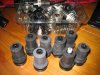

These spring boots are from other Pioneer suspended steel subframe Quartz Lock DDs. I wonder if they are the same?

Roughly 22mm diameter, 33mm length, 29.5mm outer rubber spring skirt at bottom, internal spring diameter approx 20mm.
Those look intriguingly similar. The part number would do the trick, or the model of the units they came off of.
Enjoy,
Rich P
PL-630 Success story
My recently acquired PL-630 came down with severe speed control problems soon after my purchase. I found this thread and long story short - my speed is rock-solid now. I resisted the urge to perform a full re-cap (for now, any way) and just followed the directions in this thread to clean the user speed control switches. This required de-soldering the switches to get inside them and clean the black contacts (which are now silver), then re-solder them back on.
A very satisfying repair!
Next mission: what do do about the feet. The rubber boots were well beyond repair. Ideas?
Thanks Rich
My recently acquired PL-630 came down with severe speed control problems soon after my purchase. I found this thread and long story short - my speed is rock-solid now. I resisted the urge to perform a full re-cap (for now, any way) and just followed the directions in this thread to clean the user speed control switches. This required de-soldering the switches to get inside them and clean the black contacts (which are now silver), then re-solder them back on.
A very satisfying repair!
Next mission: what do do about the feet. The rubber boots were well beyond repair. Ideas?
Thanks Rich
restorer-john
Addicted Member
No part numbers too long ago- I stripped them from Pioneer DD tables many years ago. IIRC single point strobe, stable hanging rotor PLL QL DD semi and full autos. Nasty cheap S-shaped arm, cheap auto mech but lovely motor (I stripped them for the motors) and angled edge platter. Low profile and metal suspended under chassis.
PL300/400 IIRC?
PL300/400 IIRC?
The tonearm pick-up plate is likely improperly positioned, and is likely split at the shaft interface. Look above for what such things look like.Incredible thread! The tonearm for my PL-630 when pressing start seems to be trying to swing in the wrong direction! I'm guessing photoeye or a switch is out of alignment. Any guesses anyone?
Enjoy,
Rich P

Van73
Active Member
Split at the shaft? As in broke/damaged? If so, hopefully this something that a DIY repair can take care. I hope it isn't damaged though. Thank you for helping.The tonearm pick-up plate is likely improperly positioned, and is likely split at the shaft interface. Look above for what such things look like.
Enjoy,
Rich P
The pick-up plate shares the shaft that the tonearm rotates on. It reveals specific tonearm positions (optically) to the tonearm drive circuitry. It is held in place by a single set screw. The pressure exerted by the set screw causes the plastic of the pickup plate to split, making it impossible to properly tighten the pickup plate in position, and distorting its shape when you try. Here you should find the correction for the split: https://audiokarma.org/forums/index...er-pl-630-turntable.92333/page-7#post-8147984 and you should see it here: https://audiokarma.org/forums/index...r-pl-630-turntable.92333/page-10#post-9717690 The correction is not too hard, if you are careful and accurate.Split at the shaft? As in broke/damaged? If so, hopefully this something that a DIY repair can take care. I hope it isn't damaged though. Thank you for helping.
Enjoy,
Rich P
Last edited:
Van73
Active Member
The pick-up plate shares the shaft that the tonearm rotates on. It reveals specific tonearm positions (optically) to the tonearm drive circuitry. It is held in place by a single set screw. The pressure exerted by the set screw causes the plastic of the pickup plate to split, making it impossible to properly tighten the pickup plate in position, and distorting its shape when you try. Here you should find the correction for the split: https://audiokarma.org/forums/index...er-pl-630-turntable.92333/page-7#post-8147984 The correction is not too hard, if you are careful and accurate.
Enjoy,
Rich P
 We are not worthy of your excellence! Thanks for your help. I'll dig into things this weekend and let you know.
Binkman
Lunatic Member
Just adding;
Service manual http://www.vinylengine.com/library/pioneer/pl-630.shtml
This is very similar in operation as the Technics sl-1600 mk2. Not sure about 'cracked plate' issue. However the arm has two micro switches that must be centered on the cam gear. Both switches would be normally 'on' when centered. quick dmm check is easy. If one of these switches is off center that will cause the tone arm to operate as latest post of erratic movement with SS button. Cleaning and Relubing the worm gear is highly recommended, possibly a new belt.
After making sure the s1 and 2 micro switches are centered arm should be resting dead on the rest post. Let the unit warm up about 10 minutes if not used in a long time and don't touch any switches. This will allow the controller ic to reset itself. This is not instant on technology and caps likely need to reform a bit. My 1600 works flawlessly after about a 2 minute warm up using either SS or the up down cue button. Note that I powered on and off without touching any buttons a few times over a couple hours. made a couple of adjustments here and there for needle drop and pitch but warm up was the major factor.
Hope it helps.
Service manual http://www.vinylengine.com/library/pioneer/pl-630.shtml
This is very similar in operation as the Technics sl-1600 mk2. Not sure about 'cracked plate' issue. However the arm has two micro switches that must be centered on the cam gear. Both switches would be normally 'on' when centered. quick dmm check is easy. If one of these switches is off center that will cause the tone arm to operate as latest post of erratic movement with SS button. Cleaning and Relubing the worm gear is highly recommended, possibly a new belt.
After making sure the s1 and 2 micro switches are centered arm should be resting dead on the rest post. Let the unit warm up about 10 minutes if not used in a long time and don't touch any switches. This will allow the controller ic to reset itself. This is not instant on technology and caps likely need to reform a bit. My 1600 works flawlessly after about a 2 minute warm up using either SS or the up down cue button. Note that I powered on and off without touching any buttons a few times over a couple hours. made a couple of adjustments here and there for needle drop and pitch but warm up was the major factor.
Hope it helps.
Van73
Active Member
Thank you. Hopefully with all of this info I'll be able to solve the problem.Just adding;
Service manual http://www.vinylengine.com/library/pioneer/pl-630.shtml
This is very similar in operation as the Technics sl-1600 mk2. Not sure about 'cracked plate' issue. However the arm has two micro switches that must be centered on the cam gear. Both switches would be normally 'on' when centered. quick dmm check is easy. If one of these switches is off center that will cause the tone arm to operate as latest post of erratic movement with SS button. Cleaning and Relubing the worm gear is highly recommended, possibly a new belt.
After making sure the s1 and 2 micro switches are centered arm should be resting dead on the rest post. Let the unit warm up about 10 minutes if not used in a long time and don't touch any switches. This will allow the controller ic to reset itself. This is not instant on technology and caps likely need to reform a bit. My 1600 works flawlessly after about a 2 minute warm up using either SS or the up down cue button. Note that I powered on and off without touching any buttons a few times over a couple hours. made a couple of adjustments here and there for needle drop and pitch but warm up was the major factor.
Hope it helps.
Binkman
Lunatic Member
Actually the worm drive and motor assembly is so close to the mk2 I'd think they are the same on the belt (actually an O-ring... Ace hardware has one and dad gummit I can't find the spare. you could take it with you. I have a thread on my mkII on TT's. if needed I'll dig it up. but the stock number is pretty common. You may need some recapping in the motor transistor circuits perhaps assure that you're actually getting 5vdc on the logic IC's, too.
Also I don't advise doing measurements with the motor asm. connected. the mkII manual advised never to operate it without the platter installed. Don't know on your unit.
Again after on and off's it may cure itself cap wise but not very expensive replacing same.
Also I don't advise doing measurements with the motor asm. connected. the mkII manual advised never to operate it without the platter installed. Don't know on your unit.
Again after on and off's it may cure itself cap wise but not very expensive replacing same.
Last edited:
First, thank you for your desire to be helpful. But, I'm sorry, the PL-630 is a completely different animal from the Technics, mechanically and electrically. The platter must indeed be installed to run the unit, yes. But I strongly advise that the motor assembly NOT be disconnected. The only time you should not power the unit without the platter, is when the platter is actually being driven. Some signals can be checked when the platter is not to be rotating. When the platter should be rotating, the platter and plinth are removed, and measuring devices are connected, as may be specifically needed, the platter is reinstalled, and the unit is run to acquire the measurements. There are no connectors to disconnect the motor assembly, and the whole system must be interconnected normally, in order to obtain meaningful operation, as well as measurement/assessment clues.Actually the worm drive and motor assembly is so close to the mk2 I'd think they are the same on the belt (actually an O-ring... Ace hardware has one and dad gummit I can't find the spare. you could take it with you. I have a thread on my mkII on TT's. if needed I'll dig it up. but the stock number is pretty common. You may need some recapping in the motor transistor circuits perhaps assure that you're actually getting 5vdc on the logic IC's, too.
Also I don't advise doing measurements with the motor asm. connected. the mkII manual advised never to operate it without the platter installed. Don't know on your unit.
Again after on and off's it may cure itself cap wise but not very expensive replacing same.
The tonearm drive belt is not an o-ring. They will not likely have it at a hardware store, but it is readily available, from a source stated early in this thread.
Replacement of individual caps is good, as they are determined to be bad. However, wholesale recapping should not be done until the unit has been fully repaired. Recapping is aimed at longevity, and is not a proper "repair" procedure.
The motor control circuitry consists of several proprietary ICs, that essentially constitute a state machine, and there is no circuitry that needs to "reset." It is, in fact, instant on...meaning that it responds to its inputs immediately upon application of power.
The 2 tonearm lifter/drive sensor micro-switches are not delicately balanced upon a cam gear. They could be bad, and I routinely replace them, out of hand. But if properly installed, Their response is entirely dependent upon the rotational position of a cam plate that reflects the current state of the tonearm lifter/drive mechanism only. If the switches need to be checked, it is a simple matter to do so, with power off, and using an ohm meter (meter readings of sub-1 ohm are required when a contact is closed, open contact problems will rarely be encountered). The lifter/drive plate may have to be manually positioned, by rotating the pulley normally driven by the motor, in order to actuate and release the switches. Tonearm position is indicated, optically, via the rotational position of the tonearm plate, which has no direct interaction with the sensor micro-switches.
As previously stated, what this unit very likely has is a mechanical issue, involving the proper orientation of a device that optically indicates tonearm position. There may be an electronic issue hidden behind it, but that won't be revealed until the mechanical problem has been corrected, or verified as inapplicable. When the pick-up plate is properly positioned, its set-screw will be aimed essentially straight to the rear, when the tonearm is in its rest.
Enjoy,
Rich P
Last edited:

Binkman
Lunatic Member
pustelniakr; Perhaps I should have said 'remarkably similar' to the mk2; in operation modes without splitting hairs? (pg 23 of the pdf file) Yes I understand the pita positioning of the screw to get the sensor 'windows' to hit on target. However erratic tone arm could also be other issues if the cpu or controller chippy isn't reset. there are logic sequences for the motor to be directed in forward or reverse. In the mk2 I had to order a logic chippy (non inverting buffer) from china to correct the motor sequence while others were telling me to recap. saved a large chunk of change$.  yay!
yay!
btw.. the belt? believe me it's manufactured the same as an o-ring if the 'belt' is round.. so I save another few bucks on that without the b.s. shipping.
Instant on? lets take all the caps out of the boards and see how instant on it is?
yay!btw.. the belt? believe me it's manufactured the same as an o-ring if the 'belt' is round.. so I save another few bucks on that without the b.s. shipping.
Instant on? lets take all the caps out of the boards and see how instant on it is?
Last edited:
Remarkably similar? Not likely. Similar in some respects? Maybe. Material to this discussion? Meh.pustelniakr; Perhaps I should have said 'remarkably similar' to the mk2; in operation modes without splitting hairs? (pg 23 of the pdf file) Yes I understand the pita positioning of the screw to get the sensor 'windows' to hit on target. However erratic tone arm could also be other issues if the cpu or controller chippy isn't reset. there are logic sequences for the motor to be directed in forward or reverse. In the mk2 I had to order a logic chippy (non inverting buffer) from china to correct the motor sequence while others were telling me to recap. saved a large chunk of change$.
btw.. the belt? believe me it's manufactured the same as an o-ring if the 'belt' is round.. so I save another few bucks on that without the b.s. shipping.
Instant on? lets take all the caps out of the boards and see how instant on it is?
This thread was created to show how to restore a PL-630 without cutting corners or using arbitrary substitutions. It is not about saving a few bucks. Folks can certainly do as they wish with their own gear. Folks with other ideas on keeping their equipment running are free to create threads to tell others how they can follow suit. This thread is made a sticky in the Pioneer restoration database, because it works to keep the gear running as close to original specs as possible, and in as close to original condition as possible. It is NOT intended as a normal discussion thread.
The belt is NOT an o-ring, Belts and o-rings are designed for different purposes, out of different materials. The belt is a square belt, and the pulleys are designed for it. The proper belt is important. If too tight, you risk burning up the tiny motor, or damaging its bushings through excessive wear. If too loose, the belt will slip, leading to inaccurate stylus positioning or erratic tonearm movement. If too stretchy (as some kind of o-ring would be), again, inaccurate stylus positioning and erratic tonearm motion. Round cross-section belts have little more than tangential contact points with pulleys designed for square cross-sections. Therefore, there is greater risk of slippage, unless the belt is tighter (smaller). Stretched belts (to get the tightness needed for wrong belts or "o-rings") dry out and age faster. Enough said about the belt. The correct ones are just too easy to obtain to worry about kludging.
There are no chips that need resetting, anywhere in the PL-630. The controls are all state machines (combinatorial logic and timing circuits), where the outputs are directly and immediately determined by the inputs. There are no CPUs in there. I have the datasheets on all of the chips, as well as their implementation and design documents.
As for taking out all of the caps...that is just foolish jesting.
I tell people NOT to recap, until a unit is fully functional. So, I do not encourage people to waste money that could be saved.
As for the chips in the unit, they are all proprietary Pioneer chips, seen only in their turntables, and a couple of their cassette decks. Anything out of China will be unfortunate counterfeits. New, replacement chips are not currently being manufactured. I could design replacements, but the non-repetitive engineering costs would be prohibitive. Need a "chippy?" You need a parts unit, or a part from someone's secret NOS collection, period.
These tables are one of my specialties. They have been for decades. I am a design engineer with over 3 decades of experience. I "know" what I am talking about. Yes, there are myriads of potential causes for various symptoms. However, given any set of symptoms, there are likely causes. I can be trusted to give them.
There is no need to begin bouncing around the room, and entering in spitting contests. If you just want to dispute with me, create a disputing thread and we can go at it there. Lets not muddy up the waters in this thread. In this thread, encouraging kludge techniques will always be resisted by me, and muddying posts are in danger of deletion.
Rich P
Last edited:

Get involved? This is my restoration thread.Hey ... have at it.. I was not trying to stir a 'pot'. so to speak. Want to get involved? okay put up your diagnosis step by step... I concede.
so you are going to solve the latter posters problem? right?
I was trying to "have at it." This thread is filled with my step-by-step diagnosis and procedure. I already sent the poster to check out and deal with his issues. He will return with further info, when he is ready, if ever.
I have done quite a few remote troubleshooting jobs on this site. Here is an example: https://audiokarma.org/forums/index.php?threads/pioneer-rt-909-trouble.655420/
Enjoy,
Rich P
- Status
- Not open for further replies.