• The move to the new server is done. There are some software and database maintenance updates in process. This has us passing the hat around to help out. We appreciate any donations. Seriously, even a dollar helps. The payment page may be found here - https://www.audiokarma.org/support.html

Restoring an AU-X1

Hyperion

Roobarb & Custard
Subscriber
After an initial listening test, which I was very pleased with, further checks have revealed some problems with the amplifier.

Right channel, cannot adjust bias, DC offset OK.

Left channel, could initially set bias, but after a slip with a probe, (comparing L&R), and 68 volts appearing on the output, one shorted driver transistor replaced - I can no longer set bias. DC offset OK (again). After replacing the driver transistor I have removed the precious original output transistors (all test OK), and replaced them with just one pair of MJ21193 / MJ21194 transistors. I will also do this to the right channel, until I get the bias issue sorted out on both channels there will be no other components changed except to resolve this issue.

I have been studying the schematic, and with the few voltage measurements I have been able to make, decided that the problem is with the bias servo transistor, OR one or more of the quad of driver transistors that follow. (one already replaced on L channel as above). Access to the driver boards on this amplifier is extremely difficult, it took me about ½ hour to remove one amplifier module - I expect to get a bit quicker as time goes on :rolleyes:

The good news is that I have correct replacements for all the driver transistors already 'in stock' :thumbsup:

More news when I have it - this will be quite a long job. :smoke:
 
Register to hide this ad
OUCH! I think I can smell the spark from here.

After my last similar episode I really make an effort to "probe" with mini-grabbers on the component side whenever possible. I have some technics for probing the track side, but very few things work EVERY time.

Good Luck - - -
 
Hi John,

Sorry to hear about the mishap, these things are bound to happen every now and then..... Hope that it doesn't cause too much grief

And you are right about the removal of the amplifier modules, if does take to time to get these out and in.

Cheers

John
 
Thanks guys, I have two pairs of mini grabbers and they were in use, but with accessibility so poor (in running condition), shorting a couple of legs of TR11 is all too easy, and TR16 decided to 'let go'. I also clip the probes on with no power applied, and also power off to remove them, I always do this in these circumstances. But I must have been too quick removing the probe on this one and the PSU voltage hadn't decayed enough - lesson learnt. :smoke:

Or should I say 'transistor burnt - lesson learnt'. :D
 
Last edited:
Hi john if you need some ksc1845, ksa992 or other stuff, please let me know. I have plenty left ;) I can send you a list if you want.


Regards
 
Hi john if you need some ksc1845, ksa992 or other stuff, please let me know. I have plenty left ;) I can send you a list if you want.

Regards

Thanks Harold, luckily I also have plenty of each - made a bulk order to Mouser a while ago. :thumbsup:
 
Do you know what version of the phono board you have? Does it have the modification on the backside of the board?
 
And now for a progress report.

As I previously mentioned, I was unable to set right channel bias, and while making measurements to compare the channels I did something to the left channel which caused the same effect. I am happy to report that I have restored the ability to set bias on the left channel, (shorted TR16 replaced) and begun working on the right channel this morning.

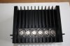
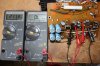
Here is a picture of the right channel heatsink, showing the right channel OP transistors only.
IMG_2043.JPG

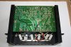
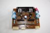
And a picture of the right channel driver board - completely untouched by me. (apart from desoldering various connections to be able to remove the module).

IMG_2044.JPG

Having taken as many voltage and resistance measurements as I could with the module in situ, I set about finding out what was wrong - expecting as with the left channel a shorted or open transistor. Knowing I could set DC offset ruled out the input FET and nine other transistors, leaving 7 to look at, I went through them all checking with my multimeter on 'diode test' and found nothing definitely wrong, but a few weird readings made me remove several to double check with my Peak Tester - all seemed good. I checked that the bias trimmer actually adjusts, and checked all diodes - all good. I checked the emitter resistors of TR10/11, TR15/16 and TR13/14, all good - and began wondering if I had some nightmare fault, like an intermittent transistor or something.

Then my eyes fell upon R36 and R37, they have the look of 'fuse resistors' (although they aren't) but otherwise look innocent enough, 390Ω - so I checked them, one measured 211KΩ and the other one was open :yikes: - take a look below - the base stoppers for the driver transistors both effectively open!
IMG_2049.JPG

I am left scratching my chin as to 'how' these came to be like that - needless to say I'll be checking the other channel as well. I learnt a lot finding these faults, I now have some extra tricks up my sleeve when troubleshooting similar amplifiers. ;)

Anyway I know what is wrong now - but... the most irritating thing... I don't have any 390Ω resistors in stock !

More later. :D
 
Last edited:
On of my R36 crumbled to pieces. I remember someone telling me to check those or better replace them ;).
I also notice that you already have 47pf for c15/c16.
 
Do you know what version of the phono board you have? Does it have the modification on the backside of the board?

I count one ceramic disc capacitor on the F-2771/0 (MM) +jumpers, and 4 film capacitors +jumpers on the F-2918/7 (MC).

Update:

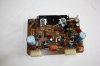
Component side MC Head Amp
IMG_2051.JPG
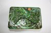
Track side MC Head amp
IMG_2052.JPG
Component side MM Head Amp
IMG_2050.JPG
Track side MM Head amp
IMG_2053.JPG

Harold, please let me know if you need any component values clarified.
 
Last edited:
And now for a progress report.

As I previously mentioned, I was unable to set right channel bias, and while making measurements to compare the channels I did something to the left channel which caused the same effect. I am happy to report that I have restored the ability to set bias on the left channel, (shorted TR16 replaced) and begun working on the right channel this morning.

Here is a picture of the right channel heatsink, showing the right channel OP transistors only.
View attachment 717120

And a picture of the right channel driver board - completely untouched by me. (apart from desoldering various connections to be able to remove the module).

View attachment 717121

Having taken as many voltage and resistance measurements as I could with the module in situ, I set about finding out what was wrong - expecting as with the left channel a shorted or open transistor. Knowing I could set DC offset ruled out the input FET and nine other transistors, leaving 7 to look at, I went through them all checking with my multimeter on 'diode test' and found nothing definitely wrong, but a few weird readings made me remove several to double check with my Peak Tester - all seemed good. I checked that the bias trimmer actually adjusts, and checked all diodes - all good. I checked the emitter resistors of TR10/11, TR15/16 and TR13/14, all good - and began wondering if I had some nightmare fault, like an intermittent transistor or something.

Then my eyes fell upon R36 and R37, they have the look of 'fuse resistors' (although they aren't) but otherwise look innocent enough, 390Ω - so I checked them, one measured 211KΩ and the other one was open :yikes: - take a look below - the base stoppers for the driver transistors both effectively open!
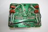
View attachment 717124

I am left scratching my chin as to 'how' these came to be like that - needless to say I'll be checking the other channel as well.

Anyway I know what is wrong now - but... the most irritating thing... I don't have any 390Ω resistors in stock !

More later. :D
Man you really are lucky, spotting those resistors.
 
Back
Top Bottom