• The move to the new server is done. There are some software and database maintenance updates in process. This has us passing the hat around to help out. We appreciate any donations. Seriously, even a dollar helps. The payment page may be found here - https://www.audiokarma.org/support.html

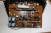
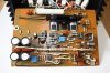
Restoring an AU-X1

Hi john, I was also referring to the version of the f-2772 board you have in your amp, just like Ron.
I removed the ceramic capacitors on the track side of the f-2270/1 MM boards, per advise from Martin Kuehne.
It seems however that you have a later version, because you already have 47pf black flags for c15 and c16 on the f-2775 board. The earlier models have 33pf here (that is what I had) and I read that someone increased them to around 133pf.
I am really interested in the details of your flat amp pcb, components and grounding sheme as soon as you are working on it. Succes.
 
Hi Harold and Ron,

I have the second version of the Phono amp Mother board, note that my AU-X1 dates from August of 1980 - so, right near the end of the production run.
 
index.php
 
Looking real good!

I have a bushel of questions, but I will just set them aside for now and just say...sweet!
 
Uhhhh John, what about the double diode? Do you leave that in the amp? I would replace it.

Regards,

Harold
 
Uhhhh John, what about the double diode? Do you leave that in the amp? I would replace it.

Regards,

Harold

Ha! - I wondered if someone would spot that, I assume you refer to D101, I think maybe I should change it for the usual 2 x 1N4148...

Update:
Done.
 
Last edited:
Here is the bushel of questions I demured from asking earlier.

What did you use for transistors 15 and 16?

Is the bias transistor TR12 still an 1845?

Did you need to add material under TR12 so that it could properly remain pressed against the heat shunt. If so, what material did you use?

Any info on caps 20,21,23 and 24?

Lastly, what replaced the "Black Flags"? Are those small, sky blue, caps silver mica or something different?
 
Last edited:
What did you use for transistors 15 and 16?

Using MJ15030 / MJ15031 - at the moment I don't know of anything more suitable, I am aware they are overkill. I haven't tried to get the originals, assuming all sources to be polluted with fakes.

Also, any changes or modifications for the bias transistor TR12? Is it still an 1845?

Yep, still a 1845.

Did you need to add material under TR12 so that it could properly remain pressed against the heat shunt. If so, what material did you use?

Yes - some self adhesive dense foam (black), and a dab of heatsink compound on the flat of the transistor - which is in contact with the driver heatsink.

Any info on caps 20,21,23 and 24?

Nichicon HE, 220µF 100V - Low ESR & outstanding ripple current spec.

Lastly, what replaced the "Black Flags"? Are those small, sky blue, caps silver mica or something different?

Murata C0G ceramic capacitors.
 
Last edited:
I am having some second thoughts about my 'choice' of driver transistors. Currently I have replaced 2SC2071 // 2SA939 with 2SC4793 // 2SA1837, and 2SC2238 // 2SA968 with MJ15030 // MJ15031 - choosing these last 2 was influenced by having the metal tab available for the collector connection.

I am now wondering if the pre-drivers 2SC2071 // 2SA939 would be better replaced with something else and 2SC2238 // 2SA968 drivers with 2SC4793 // 2SA1837 - these replacements don't have a metal tab collector, but I can get around this quite easily. Also I want to use replacements where there is absolutely no chance of counterfeits.

Note that I have damaged pre drivers and drivers - so I need to replace both pairs with complementary replacements. - any thoughts?
 
Last edited:
Hi john, I used 2sc4793/2sa1837 to replace 2sc2238/2sa968, and like you mentioned you have to do something like this:

image.jpg

and here a list for the replacements, beware of the pin out!!!
image.png
 
Driver transistors on the 'finished' driver board have now been swapped over - ready once more for re-installation to test functionality.
 
I installed the second (pictured in post #25) driver assembly this evening, can now set DC offset and Bias on the right channel - very nice and stable - I am relieved and very pleased to get both driver assembles working as they should at last.

I will now remove the left channel driver assembly and bring it up to the same condition as the right.
 
I meant to ask...Are you using the original output transistors right now, or have substituted them while the work is being done?

If you are indeed using a project substitute, what transistors are standing in for the originals?

Heck...are you going to use the originals in the end?
 
Last edited:
Yes, I am using substitute (sacrificial) output transistors at the moment - just one pair per channel - MJ21193G and MJ21194G - this is all I have on hand at the moment - it does however allow me to verify bias current flow and troubleshoot the driver assembly without fear of damaging the originals.

The big question for me is when to re-install them... when I have both driver boards reconditioned seems like a good time, as I will be able to have a 'proper' listen to it for the first time. However I am a little wary of the possibility of oscillation in the phono stages for example. I'll probably have a look with my oscilloscope and signal generator to see if I have any concerns. As you may remember, I have a (very) late model which should not have any problems, however you can never be sure with 35 year old Black Flags being just about the only thing keeping the amplifier's 'crown jewels' from oblivion.
 
Back
Top Bottom