

You are using an out of date browser. It may not display this or other websites correctly.
You should upgrade or use an alternative browser.
You should upgrade or use an alternative browser.


Ronito6
Super Member
Spot on John - 91pf not available so.... 82pf + 9pf in parallel = 91pf


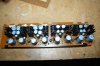
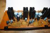
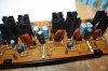
I recapped the Phono mother board, cleaned the pins, inserted and tested the rebuilt 2 MM head amps and the 2 MC head amps and set offset to spec. In my travels around these boards I found a ground lead (a 'stranded wire' jumper) that had never been soldered, luckily - and strangely, there was a second jumper - a duplicate, on the underside of the board, so no harm done. I also found an unsoldered joint on a film cap bypass at the output of one of the MM head amps, a few other joints needed attention, but nothing too bad.
As part of the preliminary checks for the above DC offset checks above, I was checking the regulated PSU ('as is') I find I can't quite set the voltages to spec, being 1V low on the -11V and around 0.5V low on the -47.5V. I suspect this is drifted resistors, out of spec zener diodes, faulty trimmers, maybe even tired series pass transistors - not to worry, this is all in hand.
As part of the preliminary checks for the above DC offset checks above, I was checking the regulated PSU ('as is') I find I can't quite set the voltages to spec, being 1V low on the -11V and around 0.5V low on the -47.5V. I suspect this is drifted resistors, out of spec zener diodes, faulty trimmers, maybe even tired series pass transistors - not to worry, this is all in hand.
Last edited:
Ronito6
Super Member
Slow and steady...
Yep. A lot o glue indeed.
Seems Sansui thought those caps would take flight.
Lacquer thinner and a chopstick, then...Bob's your uncle.
BTW: I found an un-soldered wire in mine too. It was in the left channel drive board. The grey wire that attaches to the output transistors.
Yep. A lot o glue indeed.
Seems Sansui thought those caps would take flight.
Lacquer thinner and a chopstick, then...Bob's your uncle.
BTW: I found an un-soldered wire in mine too. It was in the left channel drive board. The grey wire that attaches to the output transistors.
Last edited:
I found a possible reason why one in particular of the -47.5V adjustments was not possible, for 36 years the wrong value trimmer resistor has been fitted, 2.2KΩ fitted where there should have been a 4.7KΩ. The other reason seems to have been zener diodes which seem to be out of spec now, assuming 5% originals. I made up a very simple test circuit and the 24V zeners seem to be around 22.5V and the 6.2V zeners are around 5.8V. The same test circuit used to measure the replacements reads 23.6V (24V) and 6.22V (6.2V).
One other oddity, 4 current limit resistors which are supposed to be 12Ω as per the schematic (which read 11.7Ω) have an additional 2.2Ω (which reads 2Ω) resistor in series, there are 4 of these combinations - they all read exactly the same 13.7Ω, so, I will be leaving those alone.
Ron, your suggestion of a chopstick is a really good one, I found an old 'orphan' one and have sharpened it, it works very well.
One other oddity, 4 current limit resistors which are supposed to be 12Ω as per the schematic (which read 11.7Ω) have an additional 2.2Ω (which reads 2Ω) resistor in series, there are 4 of these combinations - they all read exactly the same 13.7Ω, so, I will be leaving those alone.
Ron, your suggestion of a chopstick is a really good one, I found an old 'orphan' one and have sharpened it, it works very well.
Last edited:
Ronito6
Super Member
Shweet. My living in East Asia pays off again. 
The 4 current limit resistors on my X1 are the same as yours.
Have you had a chance to check VR 1 and 2 on the 2778 board?
Both Harolda and I have had issues with loosing the ability to adjust voltage there. It just gets stuck at about 9.5v.
Harolda seems to have found it to be a grounding issue.
The 4 current limit resistors on my X1 are the same as yours.
Have you had a chance to check VR 1 and 2 on the 2778 board?
Both Harolda and I have had issues with loosing the ability to adjust voltage there. It just gets stuck at about 9.5v.
Harolda seems to have found it to be a grounding issue.

I only just spotted that there is a board on the schematic which appears to contain only switching, as per the schematic. But actually is described as the Buffer Amp board F-2774 - with some more components on it according to the board layout diagram.
Harold, Ron, or anyone do you have a list of components requiring replacement for this board? - it seems to have 8 EC's on it.
I am getting close to being able to look for myself, however I like to be ahead of the game.
Harold, Ron, or anyone do you have a list of components requiring replacement for this board? - it seems to have 8 EC's on it.
I am getting close to being able to look for myself, however I like to be ahead of the game.
Last edited:
Ronito6
Super Member
I only changed the capacitors and changed out the Fujitsu small signal relay for a new Omron one.
I also removed, tore down, and cleaned the selector switches and volume pots like Kale does.
This is actually one of the easier jobs on the X1.
Here is a pic of it from amp8's site.

I also removed, tore down, and cleaned the selector switches and volume pots like Kale does.
This is actually one of the easier jobs on the X1.
Here is a pic of it from amp8's site.
OK - thanks for that - loads more components on the F-2774 board layout diagram. 
What relay did you use and how did you mount it/them?... as, if it is the replacement relay I am thinking of it has a different footprint.
(sorry if you have been asked this before)
What relay did you use and how did you mount it/them?... as, if it is the replacement relay I am thinking of it has a different footprint.
(sorry if you have been asked this before)
Ronito6
Super Member
Harolda, and the late (to AK ONLY) Vintagear, and I used Omron G5V-2 as shown at Amp8's website.
Where Amp 8 modified the PC boards to accept the new relays, I simply used well insulated thick gauge wire to reroute the legs.
This graphic which I created pretty much lays it out. (Sorry for the misspellings.)

Here is what Vintagear's tech fabricated. I did the same. Works great.
http://audiokarma.org/forums/index.php?threads/the-mighty-au-x1.672322/page-8#post-9355201
Vintagear's phono board here.

Where Amp 8 modified the PC boards to accept the new relays, I simply used well insulated thick gauge wire to reroute the legs.
This graphic which I created pretty much lays it out. (Sorry for the misspellings.)
Here is what Vintagear's tech fabricated. I did the same. Works great.
http://audiokarma.org/forums/index.php?threads/the-mighty-au-x1.672322/page-8#post-9355201
Vintagear's phono board here.
Last edited:
Ronito6
Super Member
Lovely work.
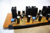
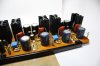
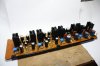
What electrolytics did you install? I'm guessing you upped the values to fit the capacitor seating spaces properly? If so, what new values did you upgrade to?
Just a sample for example.
Which multi-turn VRs did you use?
Finally, the use of ceramic insulators / spacers to lift the new VRs off the board is great.
What electrolytics did you install? I'm guessing you upped the values to fit the capacitor seating spaces properly? If so, what new values did you upgrade to?
Just a sample for example.
Which multi-turn VRs did you use?
Finally, the use of ceramic insulators / spacers to lift the new VRs off the board is great.
Last edited:
Lovely work.
What electrolytics did you install? I'm guessing you upped the values to fit the capacitor seating spaces properly? If so, what new values did you upgrade to?
Just a sample for example.
Tempting isn't it? but in this case no, all capacitance values are as the originals. They are a mixture of Panasonic FM, and the replacement range Panasonic FR (with voltages above 50V available), Nichicon HE, and Panasonic FC. These last were used because I already had the right values 'in stock', although I would have bought Panasonic FR. The 220µF 80V are actually 100V, and the 470µF 50V are actually 63V - so there are some small voltage changes.
Which multi-turn VRs did you use?
Bourns 25 turn, 3296 series 'side adjust'.
Finally, the use of ceramic insulators / spacers to lift the new VRs off the board is great.
Their main properties are not needed here, but they are a convenient way of mounting the replacement design trimmers so they don't foul, (or impede airflow around) components on the PCB. I often use them for zeners, (as seen here), or hot resistors.
Hi john, top job
Well, these are MV12's - and although they look like the infamous VD1212 types (which I would have changed without a second thought), they are not prone to failure as far as I know, so I am not thinking of changing them.
Thank you all for your kind words, (and the 'likes'
)
Last edited:
