• The move to the new server is done. There are some software and database maintenance updates in process. This has us passing the hat around to help out. We appreciate any donations. Seriously, even a dollar helps. The payment page may be found here - https://www.audiokarma.org/support.html

Restoring an AU-X1

Time for an update.

I haven't been taking as many pictures as I perhaps should have, but with a job this testing (for me anyway) I just get wrapped up in it and forget.

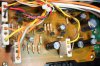
This is the finished 'Muting' PCB. F-2773
Muting PCB finished.JPG

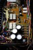
This is the nearly complete 'Flat Amp' F-2819. note the use of a single bipolar 'Muse' capacitor (green) to replace 2 back-to-back polar capacitors, and the other position shorted with a link.
IMG_2083.JPG

And now on to the Protection PCB F-2781 - this is untouched.
IMG_2085.JPG

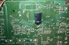
I found this on the underside, 330µF 16V across the 470µF 10V timing capacitor on the topside.

IMG_2092.JPG

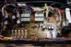
And Protection PCB finished. (need to re-dress the wiring).

IMG_2093.JPG

A number of trials and tribulations overcome along the way, such as:-

Temporary short on both -11v supplies, caused by star ground solder tag bent to wrong position.
Cannot set Flat Amp DC offset on one channel, caused by misplaced trimmer leg.
No relays firing on the Protection PCB, caused by substitute relay driver and series regulator pass transistors mysteriously not functioning, changed for different sub, all OK.

I have now 'touched' all the electronics of the amplifier. I have checked for any sign of instability with an oscilloscope - none found, so I think I am ready to re-install the output transistors and run some tests. :)
 
Last edited:
Did you exchange the cap below for new or upgraded the one on the other side / top side of it?
index.php


Also, any info on the caps you used to replace the four big 25v 4700 originals on the 2781 power protection board?

Finally, I noticed that you replace a couple of diodes on the 2781 board. Info please?
 
Last edited:
Oh yeah...forgot to ask...

Any details possible on the Kuehne ground modification?

More details on this and its effects would add quite a bit to the X1 knowledge base.

AND

"Temporary short on both -11v supplies, caused by starground solder tagbent to wrong position"

Any chance of pics and details of this problem and its solution?

THANKS!! :bowdown::bowdown:
 
Last edited:
Did you exchange the cap below for new or upgraded the one on the other side / top side of it?

I replaced these capacitors - the 470µF (topside) and the 330µF shown below like for like - the underside 330µF is now much smaller, more neatly soldered and positioned. Replacing with one capacitor ?? - who has 800µF (or 820µF) capacitors 'on hand' :dunno: :)

index.php


Also, any info on the caps you used to replace the four big 25v 4300 originals on the 2781 power protection board?

Choices fairly limited for these - I eventually used Nichicon HE, 4700µF 25V replacements, and fitted some foam padding under each one for support, as the lead spacing wouldn't allow them to be flush to the board.

Finally, I noticed that you replace a couple of diodes on the 2781 board. Info please?

I changed both zeners, and all the other smaller glass diodes including the MV12 replaced with the usual series pair of 1N4148's

I am ashamed to say that I lifted one pad when replacing components on the protection PCB, thankfully this is a rare event for me.
 
Last edited:
Oh yeah...forgot to ask...

Any details possible on the Kuehne ground modification?

More details on this and its effects would add quite a bit to the X1 knowledge base.

I performed the modification to the Flat Amp board almost exactly as shown by Harold with his 3 stage picture of how it should be done. The capacitor between the grounds on the Flat Amp, I connected right on the signal ground posts (at the end of the Flat Amp PCB), and then used thick stranded wire to connect the additional 2 capacitors to the earth tag - the now infamous tag described in the '-11V problem' in the quoted post from Ron below.

The way I see it, when you have grounds on PCB's in a fast amp like this, they have to be connected in as close to a 'star grounding' system as possible, or otherwise in a series fashion to a central point to avoid ground loops. Inevitably noise 'pickup' from various sources inside and outside the amp will cause some grounds to be noisier than others which, with the high gains and extended frequency response present, this could (and does!) cause instability. The choice of decoupling capacitor 'value' and 'dielectric' is very important here, and I think the choice of 10nF (10,000pF) capacitors is indicative of the high frequencies being dealt with by this modification. The installation of three capacitors, one to effectively short the Flat Amp grounds together at high frequencies, and 2 more to shunt both Flat Amp grounds to a star ground, is unusual in my experience, but I believe I can understand why it was done this way, even though the Flat Amp is already DC grounded.

AND

"Temporary short on both -11v supplies, caused by star ground solder tag bent to wrong position"

Any chance of pics and details of this problem and its solution?

THANKS!! :bowdown::bowdown:

Not a lot to see or describe really, I had bent the tag, (located on the chassis member in between the driver amp modules and the phono amps), upwards to tighten the screw I think? - and had forgotten to bend it down again. This meant that when I re-installed the phono amp boards 2 of them shorted on this tag and caused the problem. 2 minutes to find the problem and 30 seconds to reform the tag - done.
 
Last edited:
I performed the modification to the Flat Amp board almost exactly as shown by Harold with his 3 stage picture of how it should be done. The capacitor between the grounds on the Flat Amp, I connected right on the signal ground posts (at the end of the Flat Amp PCB), and then used thick stranded wire to connect the additional 2 capacitors to the earth tag - the now infamous tag described in the '-11V problem' below.

The way I see it, when you have grounds on PCB's in a fast amp like this, they have to be connected in as close to a 'star grounding' system as possible, or otherwise in a series fashion to avoid ground loops. Inevitably noise 'pickup' from various sources inside and outside the amp will cause some grounds to be noisier than others which, with the high gains and extended frequency response present, this could (and does!) cause instability. The choice of decoupling capacitor 'value' and 'dielectric' is very important here, and I think the choice of 10nF (10,000pF) capacitors is indicative of the high frequencies being dealt with by this modification. The installation of three capacitors, one to effectively short the Flat Amp grounds together, and 2 more to shunt both Flat Amp grounds to a star ground, is unusual in my experience, but I believe I can understand why it was done this way.


Not a lot to see or describe really, I had bent the tag, (located on the chassis member in between the driver amp modules and the phono amps), upwards to tighten the screw I think? - and had forgotten to bend it down again. This meant that when I re-installed the phono amp boards 2 of them shorted on this tag and caused the problem. 2 minutes to find the problem and 30 seconds to reform the tag - done.

Ah! Gold!!:jump:

Many thanks for the details and patience with my noobishness.:D
 
I replaced these capacitors - the 470µF (topside) and the 330µF shown below like for like - the underside 330µF is now much smaller, more neatly soldered and positioned. Replacing with one capacitor ?? - who has 800µF capacitors 'on hand' :dunno: :).

Just for future reference, note that 820µF is a standard value; Mouser stocks this size with 3.5mm, 5.0mm and 7.5mm lead spacing variants: http://www.mouser.com/Passive-Compo...Z1z0yoh6Z1yx4aw3Z1yqjoa3Z1yx4awy&Ns=Pricing|0
 
Thanks Lee, I am aware it is a standard E24 value, but I just don't have one 'on-hand', finding that 330µF under there was a 'Sansui special' surprise :) - I have most values up to 470µF, but not 820µF, I also only buy 1000µF when I need them, BTW - there are 14 of these in the AU-X1. :D
 
Last edited:
No further work done on the amplifier so far (since post #103 mentioning testing), home and work matters have intervened. Hopefully I will get some time this coming weekend.
 
Update: With the sacrificial OP transistors still installed (1 pair per channel), I get output, only testing at very low levels at present - controls and switching seem to work, sine wave output looks fine, and a beautiful square wave output albeit at 1kHz, that you could chop parsley with :D

Next steps
Try frequencies up to 20kHz.
Then back the bias down, so it reads just a 'sniff' of bias.
Remove output modules and re-fit original OP transistors, refit modules.
Adjust DC offset, re-adjust bias and perform same tests.
 
Last edited:
Just catching up on this thread - CONGRATS John on a meticulous and thorough restoration on this classic. One can only hope to have the skills someday. May you chop parsley all the way up to 20 Khz and enjoy the fruits of your labor. :thumbsup::thumbsup:
 
Thanks Tom, this has been quite a testing project for me, had to 'pull out all the stops' so to speak. :D - however, I remain in the shadow of Harolda's and Ronito's restores, and have been helped tremendously by both.
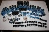
There are still a number of problems to surmount if I want to go the whole distance - like the 8 x 10000µF main smoothing capacitors - nothing of the correct size available now. (all seem to be ~50mm diameter, but really need 40mm diameter). I have a solution for the 2 smaller dual 2200µF can capacitors (re-stuff), however, restuffing options are severely limited if not impossible for the bigger ones.

Anyway the 'can capacitors' are 'phase 2' - I want to get 'phase 1' done and have a good listen :music:

That's all for now.
 
Last edited:
Back
Top Bottom