• The move to the new server is done. There are some software and database maintenance updates in process. This has us passing the hat around to help out. We appreciate any donations. Seriously, even a dollar helps. The payment page may be found here - https://www.audiokarma.org/support.html

Rotary SUT Load Switch

AvFan

Super Member
I'm wondering if there is a way to use a rotary switch with my SUTs to conveniently adjust cartridge load.

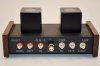
I included RCA jacks when I assembled my SUTs to allow fine tuning of the cartridge load:
DSC_0161.jpeg

This method of load refinement works well but it oftentimes isn't all that convenient. I may not have the right load plug available, it would be nice to hear the changes during playback and I have to reach around the back of my gear cabinet. A rotary switch on the front of the SUT would be a nice way to go.

This Zesto SUT appears to have the MC load switch I'm trying to find:

Allasso-beauty-shot-renumbered-croped-web.jpeg

What kind of switch is that? I think it would need two resistors (one for each transformer) at each position and probably make a hard break between positions so as not to add (parallel or series?) the resistors. It needs to be a high quality switch given the minuscule voltages.

I've also been thinking about how many load options (aka switch positions) and I don't think I'd need more than 10 with the first one having no resistor but more positions would be OK too. Thanks!
 
Register to hide this ad
If you want 10-12 load positions per channel on a single switch, you need a 2-deck switch (2 x 1P10-12T). Quality switches are expensive, $30+. eg. Grayhill:

https://www.mouser.com/ProductDetail/Grayhill/71B36-02B10S?qs=ls7QRyWmRk4RHDA3hvqgnQ==
https://www.mouser.com/ProductDetail/Grayhill/71BF30-02B12N?qs=ls7QRyWmRk7GD1eeNhYmUQ==

If you can live with 6 load positions per channel, it can be done on a 1-deck switch (2P6T), roughly 1/2 the cost.

https://www.mouser.com/ProductDetail/Grayhill/56D30-01-2-AJN?qs=ls7QRyWmRk5kbJ8AGS43yA==

Both types are available in solder-lug and PCB mount.

Then it's just a matter of choosing resistor values.
 
@HalfApt: I looked at those Grayhill switches and thought they might work but I had no idea how many decks or poles were needed for my application. Thanks so much! Yes, they are pretty expensive and I'm thinking about loading the switch with Takman or similar resistors that may exceed the cost of the switch! Mouser also has bezels for the various number of switch positions which is very handy. If Wyn's MM preamp has a 1M or 2M load resistor I can essentially have all the cartridge load on the primary/cartridge side of the SUT which is recommended by some. The cool thing is I can select a range of resistors and therefore cart loading based upon the cartridges I'm likely to use. Right now that is the Ortofon Cadenza lineup and maybe a used Windfeld or A-90.

Thanks again!
 
Why not build your own?
Google DIY Stepped Attenuator.
 
Last edited:
Sean designed these for the Wyn pre amp for resistors but I think caps would fit in there as well if that what you wanted as well.

51077216962_e86b633e79_b.jpg


Here it is with resistors but caps should also fit, I think I tried to fit smaller WIMA caps and they
did fit.

51008263605_d746e02fd6_b.jpg


P3 and P4 would go to GND for left and right and P1 and P2 for left and right signal.

The Greyhill would mount to the faceplate body. You might need to order a stopper washer with the little nub that you'd drill a spot on the face plate to hold it so incase the nut slips the whole knob wont move while selecting the capacitance load.

Athanasios
 
the size is , 56.1 x 25.1 mm or 2.21 x 0.99 inch

Athanasios

Those boards are pretty cool. So, if I want twelve loads using resistors I'd need two boards, one for each channel? Are the capacitor locations in parallel or series (Zobel Network) with the resistors? I have no idea how to implement a Zobel Network but it looks like the board would allow one if the caps are in series with the resistor(s).

Do you know if there are any of these boards available?
 
AvFan, we can order enough for both of us and may save a buck, or 2.

I'm also wondering if they can be implemented to work with a SUT. We can let one of the smart guys at AK figure out the wiring for us;)
 
Those boards are pretty cool. So, if I want twelve loads using resistors I'd need two boards, one for each channel? Are the capacitor locations in parallel or series (Zobel Network) with the resistors? I have no idea how to implement a Zobel Network but it looks like the board would allow one if the caps are in series with the resistor(s).

Do you know if there are any of these boards available?

That switch is only for 6 values as its a stereo switch. So 6 values of resistance would need 12 resistors , where each value would need 2 resistors of the same value.
The resistors and caps are in parallel .

So as I stated in the previous post the pads that are connected to the GND plane are P3 and P4 and those would connect to the GND of the RCA's and P1 and P2 are the signals and would connect to the
signal of the RCA.

The Cap location is there if you used this on the Wyn pre amp board. If you were to use this for a SUT you'd have to find a valuer suitable for most MC cartridges. However if you wanted to be able to change the capacitance value of your load on your SUT you could wire the cap locations on the switch board to your existing Load RCA jacks on the back panel and make capacitor load plugs for what ever MC cart is needed.


Does this make sense? I am pretty sure this is how you would implement this board to your SUT.

Athanasios
 
I'm also wondering if they can be implemented to work with a SUT

I would think so. The switch will rotate in resistors on either the primary or secondary side of each transformer the same as the load plugs we've wired in. I need a little more info on the type of switch and the boards.

@Nashou66 : Thanks for the clarification on the number of load positions: 6 and it is done with one board. 6 may not be enough load options, I need to think about that. My thought is to add this switch to a SUT for MC cartridges like the Zesto so I don't think I would add any capacitors, just resistors.

It might be easier, and maybe cheaper, to just get one $30 single pole, twin deck rotary switch and have 10 or 12 loading positions. It will look pretty gnarly with all those resistors all around the switch. I wonder if there is a benefit to higher quality resistors (e.g. Takman) if the load is applied to primary/cart side of each SUT?
 
3 boards cost about 11 bucks.

Maybe Sean could whip up a 12 switch version that is smaller and easier to implement into a SUT.

In the Wyn palmer thread or maybe it was my build thread he posted some pics of a similar board. I think it have more locations for resistors .

Athanasios
 
@Nashou66 : Thanks for the clarification on the number of load positions: 6 and it is done with one board. 6 may not be enough load options, I need to think about that. My thought is to add this switch to a SUT for MC cartridges like the Zesto so I don't think I would add any capacitors, just resistors.
That's a very custom switch board, designed to directly "plug-in" to Wyns LOMC board. Rather overkill for your needs.

I already have small resistor-only board designs using the Grayhill 56 series switches.

6-position stereo:
Load-switch-scale-1.jpg

10-position mono:
Gain-switch-scale-1.jpg

See them in use here: Leach MC pre-preamp

And if you want a 10/12 position, 2-channel, on a single shaft, I had a prototype for that too. Not finished, but close, depending on resistor orientations & solder pad locations. Grayhill 71 dual-deck:

select-plan-1.jpg
 
Dredging up a thread I started a while back since I'm getting a couple of Palmer V3.2 preamp boards and want to include panel mounted rotary load switches. I like the board designs @HalfApt and @Nashou66 showed but a single switch like the one @HalfApt linked, while expensive, is what I'd like to use. However, I can't find any info on how to install the resistors and then wire it to the preamp board.

This is the switch from Mouser that is in stock and I think will work: https://www.mouser.com/ProductDetail/Grayhill/71B30-02B12S?qs=ls7QRyWmRk45wW5P/4jpHA==

Does anyone have info on how the switch above should be loaded up with resistors and then connected to the preamp board? Also, I assume the rotary switch should be as close as possible to the preamp load attachment points but if not, how far can it be?
 
..... This is the switch from Mouser that is in stock and I think will work: https://www.mouser.com/ProductDetail/Grayhill/71B30-02B12S?qs=ls7QRyWmRk45wW5P/4jpHA==

Does anyone have info on how the switch above should be loaded up with resistors and then connected to the preamp board? Also, I assume the rotary switch should be as close as possible to the preamp load attachment points but if not, how far can it be?
The 2 end wires plug in to the main board in place of the on-board load resistor. Each switch deck is wired the same.

Switch wired.jpg

Can't tell ya what length of wire is acceptable as I'm not an EE. I don't think added resistance is an issue, as wires would only add a small fraction of an ohm, but radiated hum/noise pickup might be an issue. I would at least use twisted pair or coax.

Ideally (but not necessarily), it would be mounted as close as possible to the inputs, with a shaft drive to the front panel. But that would only be possible with the PCB mounted version of the switch (or you'd have to jury-rig a bracket to mount the solder lug switch).
 
Here is the load switch I used and if fits into the onboard Load resistor as Sean mentioned above. Or it may be the on board cap location. but either will work. I think I used the cap location for the load board and used the resistor location to put the load cap there. It just worked out better for me that way , and as you can see I did not populate the load cap on the resistor board.

51008263605_d746e02fd6_b.jpg


I used a bread board to hold the pins I used perfectly straight and at 90° to the main board.
The board slides right into he existing sockets and can be removed.

Here you can see I used the cap location , when we were thinking of how to implement it we realized the WIMA caps were in the way of the board to put it in the resistor location so used the cap location instead.

51008290880_7fe33dae8a_h.jpg


I used a long shaft to adjust the load from the front .

51082708062_f4cbc56a0b_b.jpg


Athanasios
 
Just realized I posted earlier in the thread about this.

I'll leave the second post anyhow . ;)

Nashou
 
Back
Top Bottom