AvFan
Super Member
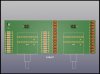
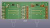
The 2 end wires plug in to the main board in place of the on-board load resistor. Each switch deck is wired the same.
View attachment 2719432
Can't tell ya what length of wire is acceptable as I'm not an EE. I don't think added resistance is an issue, as wires would only add a small fraction of an ohm, but radiated hum/noise pickup might be an issue. I would at least use twisted pair or coax.
Ideally (but not necessarily), it would be mounted as close as possible to the inputs, with a shaft drive to the front panel. But that would only be possible with the PCB mounted version of the switch (or you'd have to jury-rig a bracket to mount the solder lug switch).
That layout sketch is very helpful. Thank you! As you note and @Nashou66 shows on his build the ideal is that the loads are close to the board and I'm looking at a variety of layouts inside the enclosure to accomplish that. Turning the board 90 degrees from what @Nashou66 did and if the enclosure is wide enough then I could put the switch off to the side and avoid having a long shaft over the board. Regardless, twisted pairs will be used.
@Nashou66 : How did the shaft connect to the back of the front knob? I will probably have to make some brackets should I put the load switches towards the back of the enclosure.
FYI, Mouser has a 12 position 30 degree throw switch faceplate that matches the Grayhill switch I linked in post #17. I like the faceplate numbered so I can change out resistors or capacitors if needed. I'll just have to tape on the enclosure a list of what each number represents.


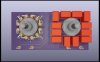
 ......Had to think about that for a minute , but now I see it.