• The move to the new server is done. There are some software and database maintenance updates in process. This has us passing the hat around to help out. We appreciate any donations. Seriously, even a dollar helps. The payment page may be found here - https://www.audiokarma.org/support.html

Rotary SUT Load Switch

Yes, that's the way it's typically done.

All resistance is done by one switch, all capacitance done by the other switch.

Switch SW1 controls resistance, switching the same resistance to both channels.

Switch SW2 controls capacitance, switching the same capacitance to both channels.

Were you expecting specific pairings of R & C on the same switch?

That's an entirely different board layout, and would still require 2 switches, one for each channel (or a single 4-deck switch vs. two 2-deck switches).
This layout works. Two switches, one for resistance, the other for capacitance.

If one switch is used, I just leave the opposite side of the board blank.?
 
Wow, how many did you order? Minimum order is three. If you can do with two, one will do me just fine.


As envisioned the resistance and capacitance loads are separate so dial in what you want for each. Yes, two Grayhill switches for a MM and probably only one for an MC since most MC carts don't care about capacitance. However, you could add another switch and caps if you find a MC cart that is sensitive to different capacitance like Wyn did with his cart.

Since both load caps and resistors are in parallel I don't think there is any reason you couldn't put resistors on the capacitor load switch if you had space and needed more resistance loads (value would be calculated as parallel resistors).

My plan is to have both resistance and capacitance loading switches for my V3.2 MM and one switch for resistance loading of my V3.2 MC. My last switch board will be for my original idea of including a SUT load switch on the primary side of my HM-7s. One of the positions in the MM resistance load switch will be 1Mohm to pair with HM-7 SUT.
 
^^^messed that up. I ordered a minimum, three. More than I need but there's no way around it.
 
"If you can do with two, one will do me just fine."

Actually, I need 3. We need to find someone to fill out our dance card for a total order of 6. Anyone?
 
I can't picture the SUT load switch. If I can I'll use one of my extra boards for that also.
 
Yes, that's the way it's typically done.

All resistance is done by one switch, all capacitance done by the other switch.

Switch SW1 controls resistance, switching the same resistance to both channels.

Switch SW2 controls capacitance, switching the same capacitance to both channels.

Were you expecting specific pairings of R & C on the same switch?

That's an entirely different board layout, and would still require 2 switches, one for each channel (or a single 4-deck switch vs. two 2-deck switches).
If the resistance side is used and the cap side isn't but, I need a fixed value on the cap side, I suppose I just solder in the value needed on the phono stage board?

edit; going over the pic's, there might not be any room if header pins are used to mount the switching board. May have to come in from the bottom with a cap or, go remote like my original plan
 
I can't picture the SUT load switch. If I can I'll use one of my extra boards for that also.

For loading the primary of the SUT one side of the switch goes to ground and the other to the signal post of the input RCA. That is how the load plugs work.

If the resistance side is used and the cap side isn't but, I need a fixed value on the cap side, I suppose I just solder in the value needed on the phono stage board?

That is how I was going to set up the V3.2 MC. I was going to just solder in a 100pf cap if one is even needed.
 
If the resistance side is used and the cap side isn't but, I need a fixed value on the cap side, I suppose I just solder in the value needed on the phono stage board?

edit; going over the pic's, there might not be any room if header pins are used to mount the switching board. May have to come in from the bottom with a cap or, go remote like my original plan
The header pins align with the phono board load resistor pads. The load cap pads are still available.

Or, just solder 2 caps on the switch board, direct to the switch common pins.

Cfixed.jpg
 
Last edited:
no need I'll pay shipping . but in an envelope with folded card stock should be fine at the cost of a single stamp, so yeah lol .

Athansios
 
Just ordered mine with some of my switch boards and the older single load switch Sean designed for me. I should be set for 5 more builds now :D

Athanasios
 
I ordered my three boards.

Thank you @HalfApt for designing the board multiple times, answering my questions and uploading the design to OshPark. What you did is AK at its best. I'm looking forward to using them in V3.2 preamp and SUT builds.
 
... Thank you @HalfApt for designing the board multiple times, answering my questions and uploading the design to OshPark. What you did is AK at its best. I'm looking forward to using them in V3.2 preamp and SUT builds.
You're welcome. I hope it all work out as you want.

For everyone: here's some info on populating the caps & resistors, links for suitable switches, and a schematic.
 

Attachments

Greyhill ordered.

I need to remember to get the stops adjusted.

And I just got an e-mail from OskPark that the boards are being made right now!! :D

Excited even though I probably won't begin another build till mid winter.

Gotta restore a Yamaha B-2 and the grand daddy of V-fets a B-1 :D

Athanasios
 
I'm resurrecting this mothballed thread in hopes @HalfApt or others can clear up my confusion since I'm about to incorporate the switch PCB in a V3.2 build.

Each switch serves both channels. If you don't populate the cap side, you've got resistive loads only. And vice-versa.

BTW, either side can be used for R or C, but the footprints aren't the best match.

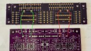
Do the both the GREEN and RED connections shown below need to be made, even if only one switch is used, to apply the paired resistors or capacitors (e.g. R1/R13, C12/C24) of each switch to both channels?

IMG_5545.jpeg

Notes:
1. J1/J3 on the switch PCB are directly above R1 on the V3.2 board and J2/J4 are directly above R2 on the V3.2 board.
2. The Greyhill rotary switches that fit the switch PCB are now $45 each up from $31 when this thread started.
 
Last edited:
Back
Top Bottom