• The move to the new server is done. There are some software and database maintenance updates in process. This has us passing the hat around to help out. We appreciate any donations. Seriously, even a dollar helps. The payment page may be found here - https://www.audiokarma.org/support.html

Rotary SUT Load Switch

This about as good as can be with thru-hole parts. More minor tweaks before finalizing, but I've got a couple of busy days ahead, so further work will have to wait.

What version of main board will you use it on?

View attachment 2720706


Might be hard to find an adjustable stop version, Mouser doesn't stock them. 10-position switch will work on the same PCB, just omit 4 resistors and/or 4 caps.

Use a shorting switch (make-before-break) for the resistors. Caps won't matter.


Looks good ,I may need to get the gerbers as well, but Is there any way to have headers line up right over the existing load sockets? Single pin headers would be fine.

Athanasios
 
... I'll have to look at the PCB switch versions but the standalone switches have holes for pins that act as stops.
Greyhill makes all their switches in adjustable-stop versions, it's a matter of finding them in-stock. Mouser doesn't have the 71 series in-stock. Someone else may.
Were you able to fit in 1/4 watt resistors or are those 1/8 watt?
1/4w, same as used on main board.
What caps did you assume?
Footprint for 5mm pitch pins. Max size 7.5mm long x 2.5mm wide, PP film or MLCC ceramic. Caps larger than that would require a proportional increase in board size.
Last question: How are the positions paired? For example, 1 and 13, 2 and 14, etc.
Yes. Pin-for-pin correspondence to switch pins.

On further pondering, there may be a bit of concern. With mounting holes at rear corners, this board will be fully cantilevered out. I have no idea how heavy the board will be with both switches & all the parts, so it may need some kind of vertical support at the front corners. Rigid drive shafts to front panel may or may not suffice. Keep that in mind for the rest of this post.

Q: do you want the interconnect wires on a socket/header as depicted it the previous example? or directly aligned with the main board load resistor pads as shown in this example?
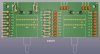
RC-loads-8s.jpg

There are other ways to do the layout as well.

This one moves the mounting holes forward, alleviating cantilever concerns, but the board is no longer flush to the end of the main board, extends backwards a bit, and it's not possible to align the wire pads with the main board.
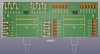
RC-loads-9s.jpg

And this one reduces board size as much as possible. Cantilever not AS much, but still more than the above. The circles on either side of J1/J2 indicate where direct alignment to main board pads would be.
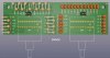
RC-loads-11s.jpg

Having said all that, IMHO, surface mount parts provide the ideal solution. Produces the smallest board, cleanest, shortest copper tracks, with multiple mounting hole options.
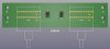
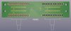
SMD-switch-side.jpg

SMD-part-side.jpg

Here's the "X-ray" views showing copper traces. Thru-hole far more complex than SMD (1206 size SMT shown)..

Thru-hole:
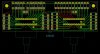
tracks-tht-11.jpg

SMD:
tracks-smt-2.jpg
 
Looks good ,I may need to get the gerbers as well, but Is there any way to have headers line up right over the existing load sockets? Single pin headers would be fine.
What main board version? My examples are for v3. v2 would require some changes, notably a longer board, as the main board pads are inset further than v3.
 
What main board version? My examples are for v3. v2 would require some changes, notably a longer board, as the main board pads are inset further than v3.

I don't think I have any v2.xx left, all should be v3.x Some are the red version.

Athanasios
 
On further pondering, there may be a bit of concern. With mounting holes at rear corners, this board will be fully cantilevered out. I have no idea how heavy the board will be with both switches & all the parts, so it may need some kind of vertical support at the front corners. Rigid drive shafts to front panel may or may not suffice. Keep that in mind for the rest of this post.

Q: do you want the interconnect wires on a socket/header as depicted it the previous example? or directly aligned with the main board load resistor pads as shown in this example?

I noticed it was cantilevered so maybe the switch board can be widened enough to provide four mounting holes beyond the width of the V3.2 board. The width of the switch board isn't a big deal for me but it may be for others. I like the idea of pins from the new board that slide into the loading holes on the V3.2 board. If additional mounting holes aren't an option at least those pins could be soldered and provide some support. Extending the switch board beyond the narrow edge of the V3.2 board is also fine to me but others might not like loosing the direct connection to the holes on the V3.2 board.

I know the traces using through holes are more complex but it would be easier for me to swap out in the future a resistor or capacitor should I want to change things up later. I'm going to use a numbered (1, 2, 3 etc) switch faceplate versus the actual load value to provide future flexibility.

I just looked at Digi-Key and they don't have any of these switches either. That could be the biggest issue to be resolved before this idea could be implemented.

Thanks again!
 
I just looked at Digi-Key and they don't have any of these switches either. That could be the biggest issue to be resolved before this idea could be implemented.
Only the ADJUSTABLE versions are non-stock. Mouser has the fixed-stop in-stock.

This should work for both you and Athanasios. If you don't need the extra 4 mounting holes, just cut the ears off at the white lines. Connectors align w/main board load resistor holes.

RC-loads-12.jpg

That's as far as I can go without more specific details about what you may want.
 
@HalfApt does this board design require you populate all 24 positions or can you use half?
No, you can use as many as you need, but you must use an equal number of resistors per channel on the resistor switch, and an equal number per channel on the cap switch.

The biggest problem is finding a switch in-stock somewhere that has limit stops at the number of positions you want.

These switches are made in both 10 and 12 position. Either can be used on the board.

Both types are made with the full range of positions (10/12), AND with fixed stops at 8,6,4 & 2 positions, OR with user adjustable stops...IF...you can find them in-stock anywhere.

You DO NOT want to leave any positions without a resistor, otherwise the load could accidentally go open circuit, which is bad.

OTOH, if all you need is 6 load positions (for cap or resistor) these switches are overkill at 3x the cost of a simple 2P6T switch
 
Only the ADJUSTABLE versions are non-stock. Mouser has the fixed-stop in-stock.

This should work for both you and Athanasios. If you don't need the extra 4 mounting holes, just cut the ears off at the white lines. Connectors align w/main board load resistor holes.

View attachment 2723460

That's as far as I can go without more specific details about what you may want.

That is perfect for me and hopefully for others thinking about implementing a load switch. What would be the next steps to get the board produced? Since I started all this I'm in for any setup costs etc.
 
.... What would be the next steps to get the board produced? Since I started all this I'm in for any setup costs etc.
If everything looks good, no further changes or features, I can finish up and post the gerber files for download.

Gerber files are needed at China shops, for lowest cost.

And/or I can post to OSHPark (USA) for direct order. $27.90 for 3 boards ($9.30 per board), shipped.

If going thru China, you might want to co-ordinate with the others who want boards, and get a total to order.
 
If everything looks good, no further changes or features, I can finish up and post the gerber files for download.

Gerber files are needed at China shops, for lowest cost.

And/or I can post to OSHPark (USA) for direct order. $27.90 for 3 boards ($9.30 per board), shipped.

If going thru China, you might want to co-ordinate with the others who want boards, and get a total to order.

OK, let's see if we can figure out if any folks are interested and how many of these switch boards they'd like.

I'm in for three boards.

Next?
 
I want some not sure how many yet have to see how many pre amp boards I have , but I prefer the Oshpark boards . So I may wait and get them on my own if the files become available for me to upload at a later time.

Athanasios
 
$9 a board for Oshpark get my vote.

Bill wants three, Athanasios needs? and I'll do whatever it takes to bring the talley to 9.

Or Bill and I can do three apiece???
 
Back
Top Bottom