• The move to the new server is done. There are some software and database maintenance updates in process. This has us passing the hat around to help out. We appreciate any donations. Seriously, even a dollar helps. The payment page may be found here - https://www.audiokarma.org/support.html

RT-707 cleaning and minor repair

jbrose

New Member
Hi Tape Lovers and Happy New Year!

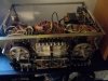
I am cleaning up one of the two RT-707s I have had in storage for a few years. This one played well a few years ago, but for one playback issue that I need to fix (and also it is quite dusty internally).

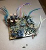
The playback issue seems to be that one rca output socket is internally broken. I can easily press on the corner of the plastic assembly that holds the rca output socket in question and wiggle plastic frame a few millimeters, but the post connected to the board does not move. See photo. Some questions if anyone can help:

1: The rca connections seem to be a one-piece assembly, not separate replaceable rca sockets. Is this correct?
2: It looks to me like the whole assembly containing the individual rca sockets is simply press fitted onto flat posts that are soldered onto the board. Is that correct? Can I simply pry the assembly off the posts?
3: if the unit is as I suspect one piece and not repairable, any ideas on how best to fix?
4:there is a pretty thick layer of dust on the top side most of the components and boards, thick enough that I am concerned it could be conductive in places. I have tried dust-off air can and that helped somewhat, and next will try a medium paint brush. Is there any spray cleaner or liquid cleaner safe to use on the boards and passive components?

thanks!
ken
 

Attachments

  • Broken-IntermittentRCAOutput.jpg
    Broken-IntermittentRCAOutput.jpg
    43.7 KB · Views: 26
Register to hide this ad
Hi Ken. Can you not just re-solder the spade connection on the back of the board? As for the dust, try a vacuum with soft brush similar to the type used to clean keyboards. I don't like compressed air as it drives dust deep into components.
 
one other question- I have a cheapo 20amp variac (non isolating) on the way so that I can power up the deck gradually. I put a wattmeter in line also while I slowly increase the voltage over about 24 hrs - in theory to help "reform" the caps.

Visual inspection shows no cap leakage or bulging problems.

I won't operate the deck until I get up to 120v.

But IIRC the capstan motor will be powered up and rotating whenever power switch is on. Could low voltage to the capstan motor damage it or anything else in the deck?

thanks again,
ken
 
Hi Ken. Can you not just re-solder the spade connection on the back of the board? As for the dust, try a vacuum with soft brush similar to the type used to clean keyboards. I don't like compressed air as it drives dust deep into components.

the spade connection is solid to the board- it does not move. it is the plastic frame and the actual rca socket that wiggles. that's why I think the socket is broken. the spade does not move but the rca socket does wiggle up and down around that lug where it enters the rca socket.

I thought about posting a video :)
 
I got much of the dust blown off with some pretty high pressure canned air. Wish I still had my diving tanks, I would rig a hose up. But my diving days are long over.

The broken RCA socket is going to be a hassle. It is actually the input rca socket, not the output. The sockets are directly mounted on the PC board as an assembly, sorry to say. First design choice I have seen for the 707 that I think is poor. Stress is put on the board when plugging cables on and off and the fact they force the cable vertical in a small space adds to the stress.

I will have to think about this. There is no place convenient I can see to mount any replacements except again, directly on the PC board.
 
thanks, I have been looking at what is available. The board and back panel of the deck expect the jacks to point up vertically with the solder lugs straight down into the board.

Looks like I will need to de-solder the whole assembly of 4 jacks since all 4 jacks are embedded into a plastic frame as one unit. Which means removing that board perhaps before doing the work.

Then solder new jacks onto the board. But without some supporting panel mounting, I expect that will be hard on the board in use.

Perhaps what I can do is semi-permanently attach short rca cables to the jacks before mounting the jacks to the board. Then I won't ever need to put pressure on the jacks after they are soldered in.
 
thanks.

there actually is no mounting plate that the jacks pass through. it is a poor design I think. and tricky to repair.

the jacks are pressed into a plastic framework that is not attached to any panel or casing of the deck. the only support for the rca jack assembly comes from the spade lugs that are soldered onto the pc board, and a couple of studs that are part of the plastic framework and sit on the board to provide further support.

So that is the challenge. The spade lugs are well soldered on the board, but one of the spade lugs is no longer connected internally in one of the rca jacks, it is broken inside the jack.

I found this better shot of the assembly...
 

Attachments

  • board rnp-451.jpg
    board rnp-451.jpg
    77.1 KB · Views: 24
as an experiment/hack I wrapped some insulated hookup wire around the plastic supporting the two input jacks and then threaded the wire through a slot of the deck's metal framework that is underneath the board and pulled tight and knotted.

That wire is now pulling the jack assembly tight against the board, no wiggling. And continuity checks out for the ground outer sleeves and the inner center connecting pins of the jacks.

So I will probably leave this as a mechanical hack and proceed with the slow voltage variac power up. I wouldn't sell the deck with that fix, but for my personal use I expect it will work acceptably.
 
Hi Ken,

check with a strong light and a magnifier. Looking at the photo, the sockets may have a U shaped spring to connect to the centre pin of the Phono Plug. The shape of the centre hole is a keyhole and not circular. If these springs have been strained then the contact to the centre pin may fail. If the U shaped springs look to be present, try slightly bending them to the centre wit a small jewellers screw driver. If have done this many times on Octal Valve bases. If the springs are of similar design then the fix is a permanent one.

Cheers

GPS16
 
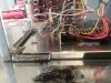
Regarding the mechanical maintenance, I have cleaned the tape transport guide assembly, it was really too slow in dropping down to off position. Now it slams down instantly which of course is not right either. So I will re-grease the solenoid connecting rod with thick silicon grease which will should retard the drop speed to acceptable level.

along with some of the "mechanical" level maintenance I may take a chance on recapping this 707.

I have not seen any obvious problems physically with the caps, no bulging, no leaking. I understand it is not possible to test the caps in circuit - or at least not with the tools I have.

So far this has been fun and encouraging results, even relaxing. That last bit might change though if I screw things up at some point. :oops:

I went ahead and purchased an rt-707 cap "kit" from audio-high-store.com web site which is in the E.U. I believe.
I used a "throw away" card so not too much risk.

Probably I can successfully perform the de-soldering and install the replacements. I have done a good amount of hobbyist de-soldering/soldering. But I do not have adequate understanding of electronics theory or testing to troubleshoot any issues that might arise from replacing the caps.

So 3 questions I guess for the pioneer experts if I may prevail upon their generosity:

1: Assuming I can successfully R&R the caps would there be any re-calibrations required just due to replacing old with new caps? I probably would not be able to accomplish re-calibrations.

2: will it be possible to replace the caps without completely removing any of the boards and cutting/desoldering the connecting wiring to the boards?

3: Is it really worth replacing all the caps if there are no obvious electronic issues and no obvious physical deterioration of the caps?

thanks!
 

Attachments

  • 20200109_202423.jpg
    20200109_202423.jpg
    75.1 KB · Views: 10
  • 20200107_162200.jpg
    20200107_162200.jpg
    94.8 KB · Views: 7
It would be a lot of work replacing all the electrolytic capacitors in one of those. And if you took on that task, you would most certainly need to make PC boards accessible and that could quite easily mean disconnecting them.

The more soldering/desoldering, the greater the possibility for making mistakes. With the number of capacitors involved, a big concern of mine would be lifting pads and traces because inevitably there will be “stubborn customers”.

I own an RT-707 and other than a counter belt and repairing a switch, have done nothing else to it. Nor would I unless there was a problem. It sounds just fine as it is. Taking on a complicated job like that “just because” makes no sense to me. I say leave well enough alone and if it ain’t broke, don’t fix it.

I learned my lesson when going gung-ho to recap a working Kenwood integrated amp. There was 95mv DC offset on one channel which I addressed by replacing both differential pairs of driver transistors. But since I was inside anyway, I sez to myself - “why not replace all the electrolytic capacitors?” Turned out to be a bad decision and the amp got parted out. Or the good bits anyway.
 
[QUOTE="I learned my lesson when going gung-ho to recap a working Kenwood integrated amp. There was 95mv DC offset on one channel which I addressed by replacing both differential pairs of driver transistors. But since I was inside anyway, I sez to myself - “why not replace all the electrolytic capacitors?” Turned out to be a bad decision and the amp got parted out. Or the good bits anyway."[/QUOTE]

Thanks, hard to argue with your thinking!
 
Hi Ken,

do not ever grease solenoids. If any damping is required it should always be external to the solenoid. The armature/stator contact should be close with no enforced gaps due to foreign bodies/substances. The 707 uses a high voltage to "Pull In" the solenoids and then drops the voltage to a smaller value to reduce the power dissipation in the coil. If there is a gap in the system then the holding voltage may not be sufficient to keep the solenoid engaged.

The shut off on a RT707 is done by a falling loop of wire next to the erase head. The wire operates a microswitch which does the Auto Stop. With no tape in place press and hold play. The loop should then fall and you should hear a clunk as the solenoid presses the stop button. The loop should take approx 2 - 3 seconds to drop. If it is way shorter than this the fluid on the loop pivot has leached out. If it is way longer than this then what is left will have dried up and gone to a paste. The pivot needs to be dismantled cleaned and fresh silicone applied.

For the Electrolytics, my policy is to do the large stressed ones in the powers supplies first. These are the main reservoir caps and are subject to quite high current pulses for every half cycle of the mains. There is also the important capacitor C408 (on RWG-070). This capacitor charges up to drop the voltage to the solenoids as mentioned above. If this capacitor goes leaky the hold voltage will rise and increase the power dissipation in BOTH the solenoids. This could "cook" the coils and give shorted turns/failure.

The small signal ones I would do "en masse" on the first failure. On a 707 it may be easier to do it by board but there is a good thread for doing this by Smurfer77. He did the whole machine at once. A very good thread which would make a good reference for anyone to follow!!

Unless you have access to the required instrumentation and the full service manual and reference tapes then I would not touch any adjustment pots or mechanical adjustments at this time. Under no circumstances adjust the screws on the heads. The Reference Tape is the only way out of that particular tweak!!!

Again, personal opinion only!

It is a good place to start.

Have fun.

GPS16
 
The transistors in this model are more likely to fail than the caps. I would replace the transistors before doing the caps. Specifically the 2SC1344 transistors. I would not be surprised if several of those are already failing (increased noise).
 
Hi Ken,do not ever grease solenoids.
GPS16"

Understood, thank you and I greatly appreciate all suggestions! So far this has been fun and relaxing, may have even lowered my blood pressure for a few hours (at least until the wife and kid show up)
 
The transistors in this model are more likely to fail than the caps. I would replace the transistors before doing the caps. Specifically the 2SC1344 transistors. I would not be surprised if several of those are already failing (increased noise).

thank you tapetech, I do see some corrosion/oxidation/discoloring on some of the transistor leads. They do look fairly easy to access and replace if necessary - easier than many of the caps anyway.

I think smurfer's detailed thread lists the transistor substitutions, I will check it out and see what is available.
 
Have not done any component R&R yet but after some careful cleaning - including pots, that famous speed control connector, tape heads, rollers, and guides, I reassembled, brought power up slowly while monitoring current consumption (never went above .3 amps while idling) and play tested.

Playback sounds excellent in my system (Transcendent Sound Grounded Grid preamp, Transcendent T8-LN OTL power amp, Reference 3A DeCapo I speakers, garden variety cables)

Although I purchased the unit used from the bay, and had it in storage for a few years, looks like I may have lucked out on this one of two 707s I own.

I won't be recording to tape, just playing pre-recorded commercial tapes. If I do make any recordings - live or archival from LP - it will be to DSD using a KORG MR-1 that I purchased for just that purpose.

In the near future I will pull #2 707 from storage and see what I can do with it. After that will come the two 909s.

I want to say how grateful I am to all the tape lovers who took the time to answer my dumb questions and make suggestions, they were a big help to me!

I am attempting to improve my skills and knowledge of electronic theory and test procedures and as I progress in that I will attempt some performance testing of the units.

Ken
 
Back
Top Bottom