• The move to the new server is done. There are some software and database maintenance updates in process. This has us passing the hat around to help out. We appreciate any donations. Seriously, even a dollar helps. The payment page may be found here - https://www.audiokarma.org/support.html

RX-770 Remote control issue. Works briefly after cycling receiver power.

Unless -- You bought the last 8 Nichicon pieces from Mouser when they went EOL about 10 years ago. :biggrin:
Got them when I was on a run of CX pre-amp rebuilds.
They are identical to the one in his photo.

That Kermet would be a good substitute. Extended memory.:thumbsup:
:biggrin::thumbsup:
 
Probably nothing wrong with the Nichicon. Test by measuring the DC voltage at pin 1 of IC306 with the power button in the OFF position. Looking for around 4.9vdc.
 
Any luck with the Oscilloscope?
Had my neighbor help with it (who is an electronics tech but doesn't work on stereos much.) Good signal and voltages on U301 when working. Signal disappears and the remote stops working after a bit, but voltages are still good. Image is when it was working.

When we first plugged in the receiver to test, it went for about 4-5 minutes with the remote working. The second and third time, it stopped working after a couple of minutes.
 

Attachments

  • RX-770-U301.jpg
    RX-770-U301.jpg
    94.8 KB · Views: 4
Had my neighbor help with it (who is an electronics tech but doesn't work on stereos much.) Good signal and voltages on U301 when working. Signal disappears and the remote stops working after a bit, but voltages are still good. Image is when it was working.

When we first plugged in the receiver to test, it went for about 4-5 minutes with the remote working. The second and third time, it stopped working after a couple of minutes.
After failure occurs, did you check the voltages at the IR receiver end of RX-770? Is the remote signal received and not processed? Or is it not received at all which would implicate the diodes (LEDs) in that section? Tell your neighbor to isolate what happens to the remote signal at RX-770.

Did you have a chance to examine the solder joints of the Rx/Tx LEDs in the remote circuitry of RS-770? I’d reflow them to be sure. Also test those LEDs out of circuit if they act funny.
 
Last edited:
After failure occurs, did you check the voltages at the IR receiver end of RX-770? Is the remote signal received and not processed? Or is it not received at all which would implicate the diodes (LEDs) in that section? Tell your neighbor to isolate what happens to the remote signal at RX-770.

Did you have a chance to examine the solder joints of the Rx/Tx LEDs in the remote circuitry of RS-770? I’d reflow them to be sure. Also test those LEDs out of circuit if they act funny.
I did check the solder joints, and they all looked very solid under the magnifying glass. Nothing at all looked suspect.
We'll check more on the voltages tonight or Friday - when he's next available.

BTW, any thoughts on component D335 which is right next to U301? Looks like an LED. We were wondering about its function in all of this and if there is a way to test it too.
 
BTW, any thoughts on component D335 which is right next to U301? Looks like an LED. We were wondering about its function in all of this and if there is a way to test it too.
I think it’s the infra-red transmitter. It’s connected to the remote control circuitry (main 9) through cables it seems or maybe traces. There’s D328 there too that maybe involved. Have to look at the schematic some more.

Edit: D335 is made by Rohm but no data on D328. I think maybe one of the U301, its supply line, or D335 is faulty. Probably U301, can’t be sure. That’s why it’s crucial to find out where the remote signal ends up during a failure.
 
Last edited:
1752111028532.png
Manual shows that C384 is a C.EL. Is sure looks like a standard electrolytic cap. Would a Digikey Nichicon 4700uf 6.3V work or does it have to be exactly 5.5V? It's almost exactly the same size.
 
Would a Digikey Nichicon 4700uf 6.3V work
No.

The purpose of this cap is to provide a 5V ~ 5.5V supply to the logic section of the processor when the unit is off (memory, etc. ). 6.3V is too high and could potentially damage the processor or parts of it. It might work but not worth the risk. There’s a reason Yamaha went with 5.5V :biggrin:
 
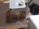
GP1U571X is the number on the U301.
 

Attachments

  • GP1U571X-873.jpg
    GP1U571X-873.jpg
    91 KB · Views: 1
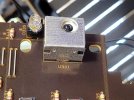
  • 20250709_210347.jpg
    20250709_210347.jpg
    116.4 KB · Views: 1
Last edited:
Sorry, it's U301.
Ok, it’s probably the infra-red receptor, shielded to prevent false triggers. Between this, the infra-red emitter, and that super cap, someone is guilty. Only the scope will show the remote control signals and what happens to them after detection. Also whether or not the detector gets deactivated after a while. Please change that cap to eliminate root causes even if it doesn’t solve the issue.
 
Back
Top Bottom