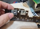
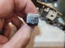
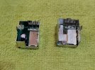
I think U301 voltages need to be checked/monitored using your neighbor’s oscilloscope before after the failure occurs. Need to find out what happens to the received remote control signal. For starters, maybe monitor U301 pins marked Vc and Vd(?) to see what happens to them during the failure. Also, keep double checking the solder work related to this chip from the power supply that provides the +12V all the way to the regulator that puts out +4.8V (Q317).
This reeks of a bad solder joint, cap, or diode somewhere. To narrow it down, need your neighbor’s oscilloscope. If someone has specific experience with this issue, I’m sure they’ll chime in.
Good work.



 I learned a lot.