Sparkplug
Super Member
No, this is 47000uF (47mF) and way more than what’s needed. The one I posted is 10mF (10000uF):This the cap you're thinking of?
View attachment 3548006


No, this is 47000uF (47mF) and way more than what’s needed. The one I posted is 10mF (10000uF):This the cap you're thinking of?
View attachment 3548006
Got it. I missed a decimal point when I was looking. It's been a long day. LOL!I made a correction to my last post, please make a note of it. The correct value is 10mF not 4.7mF as was posted above in error. The link is correct.
Got it. I missed a decimal point when I was looking. It's been a long day. LOL!


This is the most important step.Probably won't get to scope it and check some more until this weekend.
Please stay away. There’s no way of knowing how old that cap is. Except in special cases, I don’t use Nichicon these days, their idea of ±20% tolerance seems to be -20%. The one in the link is a better choice in this case.C384:
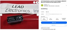
I did find the original Nichicon 4.7mf/5.5V Cap on Ebay. See image. Seller is out for a while...
If you trust your board is still OEM, always use what’s installed regardless of what the SM says. Yamaha SM’s are notorious for inaccuracies due to lack of updates.D335:
IR EMITTER (SIR-34ST3F) is also available at Mouser (if needed).
U301:
IR RECEIVER GP1U571X - which is installed on the board - I'm still looking for that.
IR RECEIVER GP1U501X which is listed in the Service manual may be available on Ebay from overseas.
B.P.F. frequencies are both 38 kHz. Sizes are identical.
I really do want to change that Cap as everything seems to be on the low side of tolerance...so Mouser parts have has been ordered and I'll let you know what more scoping around finds. Thanks for all your help so far!!The one in the link is a better choice in this case.

I really do want to change that Cap as everything seems to be on the low side of tolerance...so Mouser parts have has been ordered and I'll let you know what more scoping around finds. Thanks for all your help so far!!
Yes, the OP has already placed an order for a replacement cap (equivalent one) C384. It’ll in all likelihood fix the issue … we hope.Had to search this thread up, read it away from home and forgot the title! Anyway, you need to look through the schematic and locate the 5V computer supply circuit. Likely it is NOT switched, which is why you have to unplug it to reset it.
Since it has been powered on now for a decade or two, very likely the filter cap is are going south -- usually a + only PS, and as soon as the circuit starts to warm up it gets too much ripple and the computer stops working. The big cap is just to hold the memory, although if it's shorted it will cause trouble too by pulling the 5V line down.
I have also seen a voltage control circuit cap in a similar circuit fail as a resistor, pulling the reference voltage down so far the computer won't work. No computer, no remote.

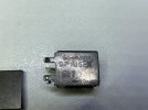
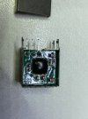
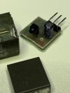
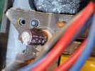
This was going to be the next step if replacing C384 didn’t work.I would be pulling the Sharp IR receiver, popping the cover and inspecting the device. They have a 'blob' silicon processor on the PCB, along with several SMD components and you guessed it, an electolytic on the topside of the PCB.
Power it up externally and test it on the bench with a DSO connected. I've had plenty of them go bad.
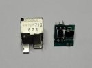
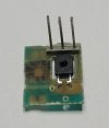
Here's a Sharp GP1U5 I prepared earlier:


No! Unless you want a memory of < 5 minutes.Would a Digikey Nichicon 4700uf 6.3V work

I'll check those caps and replace if bad.That is the memory hold cap, it is there to hold the memory while the unit is unplugged. Check the VCC (pin 1 on the computer chip) for ripple and voltage, should be 4.8V and very minimal ripple AC.
There is usually a small transformer for that circuit, sometimes just a winding on the main transformer, some sort of voltage regulation circuit, often a zener and a cap with a transistor.
Found a schematic, check C 149 and C151 (100uF and 470uF) in the 12V PS, separate "always on" transformer circuit.
Found C149...and it's empty - and there are several empty spots on that board. Table in the Service Manual shows it to be emptyFound a schematic, check C 149 and C151 (100uF and 470uF) in the 12V PS, separate "always on" transformer circuit.
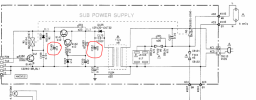
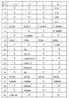
I replaced Cap C151 with a new 220uf cap as that's what the original one was. No change in remote behavior.@RS-MN ,
Based on the data provided by @restorer-john , I’d have a 47uF/10V or 47uF/16V cap ready (don’t get 6.3V rating, they don’t age as well). I think you should take the shield off of that IR module and replace that cap anyway. It’ll save headaches in the future.