• The move to the new server is done. There are some software and database maintenance updates in process. This has us passing the hat around to help out. We appreciate any donations. Seriously, even a dollar helps. The payment page may be found here - https://www.audiokarma.org/support.html

SA-8100 low volume left channel and parts list Update

centrons95@h

New Member
Hi, last year I started restoring the old SA-8100 which belonged to my mother. I changed all the e-caps (including the ltwo large ones 10 mF 50V, half of the diodes, half of the transistors and the relay. The unit works quite well and the improvement has been noticeable, but there are still some little problems so, after the pilot lamp got dead, I decided to go for a total restoration.


Problems/Questions:
1.
With some low volume input (mostly classical music LP) the left channel output is very low, sometimes muted. Same problem (with almost every source, also TUNER ) when I insert the SUBSONIC filter, or even worst the 30Hz filter. I don't know which board could be responsible for this behaviour, maybe the switch unit or the filter amp?

2. I'd like to replace all the transistors, following the list kindly provided by WyattWeeks and corrected by Markthefixer in this 2020 thread:
SA-8100 : low volume right channel problem (RESOLVED)
I couldn't find anywhere KSC2073TU and the KSA940TU which seems to be obsolete (Power Amp and Power Supply board). Are there some alternatives? Btw I am italian, so I am purchasing the parts from https://www.digikey.it/ and not from Mouser.
Schermata del 2026-04-06 18-08-53.png
3. I would like to replace the pilot lamp and the protection lamp with two leds, they have two different codes on part list, but they should be 8V 50 mA each, am I right?
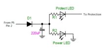
I was thinking about putting in series to the led a diode (1N4004) and a resistor (100 Ohm) , with a cap (100 u) in parallel to reduce flickering (see fig). Is this to complicated? I know there are some ready-made alternatives on ebay, but I'd prefer to do it myself (a bit of fun and a couple bucks saved).


Feel free to answer just one question (or none of course), I really appreciate this forum and the fact that there are still people who help each other out of passion. Thanks in advance!
 
Register to hide this ad
 
Sorry but I don't understand why you quote this thred. My problem seems to be different
 
3. I would like to replace the pilot lamp and the protection lamp with two leds, they have two different codes on part list, but they should be 8V 50 mA each, am I right?
I was thinking about putting in series to the led a diode (1N4004) and a resistor (100 Ohm) , with a cap (100 u) in parallel to reduce flickering (see fig). Is this to complicated? I know there are some ready-made alternatives on ebay, but I'd prefer to do it myself (a bit of fun and a couple bucks saved).
You can absolutely do that if you want.

The resistor value would be determined by the LED voltage drop and the current the LED needs for the brightness level you desire.
I find most modern LED's can be overly bright at normal operating current levels, you can control the brightness of the LED by the value of the resistor.
You will need higher than 100 ohms for this.

(or you could go crazy and make an adjustable current source or PWM brightness control) :cool:

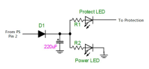
Lets say for the sake of argument that you have 10 VDC at the cap, the LED drops 3 volts across it leaving 7 volts to calculate the LED current.
We will choose 10mA as a starting point, probably too much but we have to start somewhere. To get 10mA with 7 volts we are looking at 700 ohms.

I would probably start at 1.2k myself, that would be close to 6mA LED current. FYI 100 ohms would give us 70mA and perhaps a fried LED.

sa8100leds.jpg
 
You can absolutely do that if you want.

The resistor value would be determined by the LED voltage drop and the current the LED needs for the brightness level you desire.
I find most modern LED's can be overly bright at normal operating current levels, you can control the brightness of the LED by the value of the resistor.
You will need higher than 100 ohms for this.

(or you could go crazy and make an adjustable current source or PWM brightness control) :cool:

Lets say for the sake of argument that you have 10 VDC at the cap, the LED drops 3 volts across it leaving 7 volts to calculate the LED current.
We will choose 10mA as a starting point, probably too much but we have to start somewhere. To get 10mA with 7 volts we are looking at 700 ohms.

I would probably start at 1.2k myself, that would be close to 6mA LED current. FYI 100 ohms would give us 70mA and perhaps a fried LED.

View attachment 3738039
Thank you for your detailed answer, I will try to follow your suggestions. I had roughly computed 100 ohm, because i was assuming that the current should should be the same as the one of the old lamp (50 mA, 8V), but It was probably stupid.

I don't know how many volts drop after the protection led, so I guess that R1 and R2 should be different no? Even if I use the same type of led for both protection and power.
 
Thank you for your detailed answer, I will try to follow your suggestions. I had roughly computed 100 ohm, because i was assuming that the current should should be the same as the one of the old lamp (50 mA, 8V), but It was probably stupid.

I don't know how many volts drop after the protection led, so I guess that R1 and R2 should be different no? Even if I use the same type of led for both protection and power.
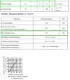
Here is some data from a generic green LED. The typical voltage drop (forward voltage) is between 2.1 and 2.6 volts.
Maximum continuous forward current is 30mA. Not shown but 10mA is the typical current.

The chart shows how the brightness changes with the current change. It is almost linear.

Every LED will have different specs, but you can get away with rules of thumb for a lot of the types we typically use.
10mA and 2.5 volt drop are a nice compromise for starters.


led.jpg

The specs for the incandescent lamps are of no use for what you are thinking about doing.

The protection LED is switched to ground via the protection relay, there is no further drop or resistance in the circuit.

The resistor values are what you need them to be for the brightness you want, bearing in mind the LED parameters and the power supply voltage.
R1 controls the current for the protection LED and R2 controls the current for the power LED, they don't have to be the same.


Ohms law is used to calculate the current with a certain resistor value, or it can be used to find the resistor value for the desired current.

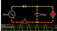
Once you know the power supply voltage at the + terminal of the cap then you subtract the LED voltage drop from it and use that voltage with ohms law.

1775686968117.png
 
Back
Top Bottom