• The move to the new server is done. There are some software and database maintenance updates in process. This has us passing the hat around to help out. We appreciate any donations. Seriously, even a dollar helps. The payment page may be found here - https://www.audiokarma.org/support.html

SA-8800 Hum problem

MAG_1944

Member
Hi Everyone

I've recently begun to use a pair of headphones with my amp for late night listening, I've noticed a low level hum which doesn't seem to change with volume.

Checks I've done so far, checking between all 4 inputs, no change.
Toggling loudness, muting, tone, high and low filters, no change
Toggling tape monitors, no change
I also took the pre amp jumpers out, no change.
I then hooked my speakers up and got very close to them and was able to notice the hum was also coming via the speakers but at such a low level I've never noticed it before in the 2 years I've had the amp. It was at this point I noticed there was a hum coming from the actual amp itself, only audible about 6" away with the case on. Its the metal cover version of the amp rather than the wooden case version

I've found 2 or 3 old threads about hum on these amps and have read though them and begun some trouble shooting to see if I can identify any issues. I've got a standard multimeter with diode test functionality but no scope or capacitor measurement ability.

Amp is a multi voltage version currently set at 240V, I'm in the UK on "240V 50Hz" but actual outlet voltage is around 247-250V depending on time of day.
I've got both the service manual and schematic and did the DC balance and Idle Current adjustments before doing anything else just encase something was off there, all adjusted to spec but no change to the hum.

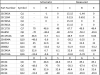
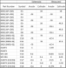
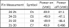
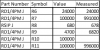
Next I made a table to go though and check all the voltages on numbered pins, diode, transistors and FETs. I've listed out the spec voltages from the schematic but please correct me if I've got anything incorrect. Full break down below

Main findings were pin 14 is giving -49.8V vs -48
Pin 15 giving -33.3 vs -32
DC voltages coming out of D9-12 were off +67.3 vs +70, and -67.4 vs -70

This is where my fault finding knowledge dries up and some input for the community would be greatly appreciated.
What other testing/checking should I be doing to establish what the root cause of Hum is, are the low voltages just a symptom of another issue I've not yet found.
One of the old threads mentioned checking the AC portion of the DC regulated voltages, is this something I should check and how would I go about doing it.
Any help would be greatly appreicated

Thanks

Mark
Pin measurements
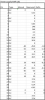
upload_2021-2-1_20-47-43.png
FETS/Transistors
upload_2021-2-1_20-48-36.png
Diodes
upload_2021-2-1_20-49-15.png

Thanks Mark :)
 
Register to hide this ad
A quick, simple test to start: pull out the pre-out /amp in jumpers and give it another listen.

We're looking to see if the power amp itself is humming, or if it is the preamp sending the hum.

edit - I now see you did that, and it still hummed.

The speaker power for the left and right channels come from separated supplies (four big caps) so listen for left or right channel differences.

PLUS, make up a pair of shorting plugs (not the 5k ohms Pioneer mentions elsewhere) and plug them into the amplifier inputs to eliminate ANY possible input to the amplifiers, again listening for channel differences.

to measure the AC on a DC voltage (like the big caps) you need to get 0.1uf of non-polarized cap (maybe mylar, but NOT ceramic disc) and connect one lead to your red probe, using the OTHER capacitor lead as your voltage probe.

Without a speaker load I don't expect much hum on them, BUT I'd have to check something here.
 
Last edited:
Thanks' Mark
Did some testing tonight, using my headphone I set the mode selector switch to L+R for the output and then dialled the balance slowly left and right, no noticeable difference between either channel. I then set mode to L and R individually but still no change.
The internal hum from the amp seems to be concentrated around the transformer and power supply board, if that's helpful
For the RCA shoring plugs would this just be a regular RCA plug with a short wire run between the internal positive and negative sections of the jack? Quick google showed some with just a wire and some with a resistor on them? Il need to get a few bits to make some up.
Assuming these are needed on every input? Got a fair few on the back to blank if so :)

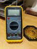
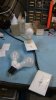
I will need to order a cap, I've not got anything in that range with a 400V rating on it. I saw in a previous post where someone was looking for a similar issue on a SA-9800 that the sensitivity of their multimeter might not have been sufficient, I've got a 20V, 200V and 700V setting is that going to be sufficient? Picture attached of multi meter if needed

Are there any other DC voltages I need to measure in the mean time?

Thanks
 

Attachments

  • IMG_20210202_191914.jpg
    IMG_20210202_191914.jpg
    129.6 KB · Views: 10
DC voltages of the 4 big caps....

shorting plugs: only TWO, on the power amp in jacks. yes center conductor wired to outer shield.
100v rating on the blocking cap will do for now for this unit. Wish my parts box was over there - got lots of them.

usually internal hum can be ignored. transformer is made of flat laminations, they usually are varnish impregnated to freeze any tendency to buzz.
stuff gets loose and buzzes. Sharp ears find it. They are called E - I laminations and they are interleaved in layers.

upload_2021-2-3_5-20-50.jpeg

images


main-qimg-c846ac82cd98cfab3479bd7d527d345c
 
Hey Mark, thanks for the explanation on the cores :)
I'm assuming a 400v rated cap wont be an issue, I'd placed an order for some 400V 0.01uf caps last night before your reply.
I will need to order some RCA jacks and wire, I don't have any spares, hopefully bits might arrive by the weekend to test.
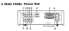
To double check just 2 are need to blank the jacks numbered 5 in the diagram from the service manual, and then all checking is done with the input switch on AUX?
upload_2021-2-3_20-20-30.png

I took the measurements for the DC across the caps by clipping onto the pins to avoid slipping with probes, let me know if that would have made any impact to the readings?
upload_2021-2-3_20-24-41.png
unit was powered on for 5 minutes to warm up before reading taken, I also checked the voltages with the unit off and noted that C7 was discharging within about 90 seconds? Is this behaviour expected?

For the VAC measurements do they need to be taken at the same points across the caps as the VDC measurements? What other points will need checking for VAC so I can build my test list up before the weekend (assuming bits arrive by then!)

Thanks for the help

Mark
 
0.1uf for the blocking cap
NOT "5", half of "6" - right side only
it does draw the attention when "one of these is not like the others" - but that effect would be limited to the one channel it is on and not both of them.
HOWEVER, it could be a bad diode that spews hum into the other channel as well.
The forcible discharge caused by a bad diode could be flowing a lot of current through the ground - inducing hum everywhere. 1N5404 (863-1N5404RLG)
C7 is fed by D5 & D7
These are soldered-in components so they should be easier to check - desoldering one lead each to isolate them for accurate testing.


best to measure ALL back at the pins
 
good thing one of us is paying attention, I had ordered a 0.1uf and not a 0.01uf. phew
I lifted the leg of each diode and checked with with my volt meter in diode test mode

D5 forward bias 0.542, reverse bias OL
D7 forward bias 0.510, reverse bias OL
also checked D13 to see if this was the reason the base of Q1 was getting -1.44 volts not -1.
D13 forward bias 0.510, reverse bias OL

Are these values what you would expect?

I also checked some of the resistors around there
upload_2021-2-4_21-11-21.png

Only R9 was off but I'm not sure if that would fall within manufacturing tolerance anyway?

If I need to discharge the main filter caps what value resistor would I need an what power rating would be suitable. Think it would be safer to get those fully discharged if I need to take any further items out.

When you say pins is that measure directly on the pins of each cap rather than the numbered board pins?
Also thinking ahead, I have a DBT ATM but we can only really get hold of 40W filament bulbs in the UK now, will I need to add a second bulb in series to have a high enough capacity for this amp?
 
Last edited:
Second bulb in parallel, 2 40W gives 80W pass through :thumbsup:, two in series give 20W pass through:thumbsdown:.
A third bulb in parallel give 120W pass through. :bigok: Use a second Y for three bulbs.

DSCF0847small.jpg

Mine are 60W bulbs, two are 120W. First power up is on 60W, then when I feel more comfortable I move to 120W to get power supplies closer to normal (without loads or music).
 
thanks for the heads up, its been many years since I did my A-level electronics :( I will stop by the hardware shop tomorrow and get a 2nd bulb holder and do some rewiring, probably also a good time to get the DBT mounted to a board rather than being a rats nest of wires.
doubled checked and my bulbs are 46w, will 2 be sufficient for this amp or do I need a 3rd?

0.1uf caps arrived today so just waiting for the RCA plugs to make blanking caps so I can start measuring the VAC.
Any suggestions on size and power for a discharge resistor for the main caps?
 
I only use a DBT to protect output transistors and proof power supplies, one the amp passes the DBT (flash bright and them dim) you are done with it. It is not used during normal testing. I have never felt the need for more than 120W, though some people do. It is extremely useful for what it does, but then its done.
 
thanks, I mainly wanted to hook it up when I first powered the unit on after lifting the components for checking just encase :)
Ok so rca plugs arrived today so I will build some blocking plugs tonight and start testing tomorrow
To confirm my test list runs as follows for the VAC checks
blocking plus in the pre amp in plugs
input to aux
negative probe hooked to chassis
Check voltage on input pin of all 4 filter caps (C5-C8)

are there any other items I should be checking with VAC at the same time to look at why Q5 is getting 67V vs 70V and Q6 getting -67V vs -70V on their gates?

thanks for all the help so far
 
I also noticed there as been an adjustment to the power supply board, in stead of R1 just going into the board it has had the side closest to the filter caps lifted and another component added in series and then connected to pin 30. Its encased in a plastic sheath so cant see if its another resistor or a capacitor.
48eS-IGYYpIhk0nG0tz4aO433gg5hFytpbXtEC-qCFVwK6iioHV_NPELVuvVjAcslfXBFY_vZOmpsf37MmR3irv86nSZx0B5yDyNod7jTUdFUOv2eKmezlTBIP1l12CniowcZ9eFfCBkRJUIoPmwrZ0hzOGpawrx_tbvR2X6hSwXse7gORnu4cjnVmdoCtrTsg9wijFGK4fI-EfHrRpjYF12a78jDKHockXmUpBb1HqTRo6uqS-MWWXC5gUIR0eCGYEXv8PBHTEuZl3ZaI03VsA1CNZ9vCipknoT9E5LikYmBqAbUqDcVt7e8wk2YEfNBtsS9oi_H1xftm7Tppn_jQlmxmqh597gO0AWeAHz0_oib7PxpeppTvk7hAVnaWq-vfUyEjj_IMvgW9BCwtxt7TF58qnVIywIeY6C8OTJ0t84yOsLI8Gd0Nrmqk71zGPbHai05nXf-91rZ84M-nDwC2ExM51_yGEB6Vgy1C794sWWNKBjCwGJOQlDi3pk_RXEYo7hOrOIy0QWZc0GzFcXtIxQ398i2XP5oW7eDsIvali8UMrkIZ8CrvEWqESyjAfCF3aramdHcyc8JpcBgrglBgdQoQyb4_-5Jiv8vpyX1mVrKq53eCxNBEYIIoxO9sZOpjJcPu-FsJ3ZjWO7J002zc_MPN04dis47gnOhz4Qk7SdNhCcZSNQLwOa632-5UE=w703-h937-no


I'm not sure if this was a factory modification or a service update, I have found a few picture on google of other units with a similar modification, including the clear sheathing over it, see below
file.php
 
ok so got the measurements taken for the VAC on the caps today using the 0.1uf cap, blanking plugs were installed in the right hand set of the pre amp pins, speaker selector to off and volume at min

had to set my volt meter to 200mv ac to get any readings at all

C5 0.025VAC
C6 0.026VAC
C7 0.039VAC
C8 0.025VAC

how does this compare to nominal and what would the next trouble shooting steps be?

thanks

Mark
 
It is as important to know what your ears were telling you - has anything made any changes?

And we still come back to the fact that there is something about C7. Faster discharge, almost double the ripple.
It does power the protect circuit and relay, and is ac sensed before the diodes for the power off/power on signal. But IS that enough? 90 seconds? maybe.
Compare the temperatures of d5 & d7, one might be (ouch!!) hotter (a sign of damage) than the other.

That's not snow around casa markthefixer, it's dandruff from all the head scratching.

What would I do? At the least swap the d5 & d7 pair with another cap's pair, swapping them about and see what happens to those 49.9v and 0.039/0.025vac readings on the caps.
IF I had some 1n5404's sitting around I would swap them in (who am I kidding - I would scope c7, it's almost double the ripple - one of those diodes may be throwing ripple.)

diode pairs:
c5 d1 & d3
c6 d2 & d4
c7 d5 & d7
c8 d6 & d8
 
hey so I checked with both headphones and speakers, thus far, with the blanking plugs in no audible change to the hum over my headphones.
I did a touch check on the diodes before I moved them and both seemed as warm as each other, not sure my finger would pass as a calibrated thermometer though :)
I've switched C7's diode pair with C8's pair tonight and my results are as follows

C5 VDC 49.9 VAC 0.026
C6 VDC -49.9 VAC 0.025
C7 VDC 49.9 VAC 0.039
C8 VDC -49.9 VAC 0.025

So even with switching the diodes the ripple has remained on C7 along with the voltage drop after shut down.
Is there anything else down stream of C7 I should be checking?

Thanks for your help :)
 
You have safely measured the AC on the unregulated DC. Now you should measure the AC volts on the REGULATED DC running the power amp.

GWH-115 Power Amp Pin 25 +48v dc regulated
GWH-115 Power Amp Pin 26 -48v dc regulated
 
Pin 25 VAC 3.9mv (VDC measured at -49.8V vs -48 in spec)
Pin 26 VAC 3.9mv (VDC measured at 48.5V vs 48 in spec)

I checked with both blanking plugs in and out and the measurement was the same each time.

thanks
 
@markthefixer are there any other items I should be checking to help dial in on the root cause? Hopefully should have a bit of spare time over the weekend to do some checking if needed?
Thanks
 
At this point I think we should find another SA-8800 and give it a listen WHILE buttoned up.

Perhaps an AC voltage measurement of the hum coming out of the power amp.
Both with a blocking cap, and without a blocking cap - while disclosing the measured DC offset at the output as well.
 
just to check, when you say power amp outputs would that be pins 15 and 20 on the power amp board or would you need them measured at the actual speaker posts with the top cover reinstalled?
Thanks
 
Back
Top Bottom