• The move to the new server is done. There are some software and database maintenance updates in process. This has us passing the hat around to help out. We appreciate any donations. Seriously, even a dollar helps. The payment page may be found here - https://www.audiokarma.org/support.html

SA-9500 II re-cap and re-build, burnt resistor help, please?

SMD88

Active Member
I am about to start working on this unit.

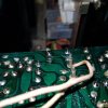
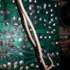
Have a small problem though, I have two fuses burnt out on the EQ board. The two on the left hand side (with the board turned up) with the coverings on body and legs. Looking at the SM, the board I have and the board in the SM are slightly different, so I initially thought these were 120 ohm resistors.

Looking at it again, I now think these are the 110 ohm resistors which I naturally cannot find in the multipack I bought when I thought they were 120! What are the best replacements for these? Can 120 be put in place of the 110? Can 1/4 watt be changed to 1/2 watt?

Thanks!
 
Register to hide this ad
SM has R29,,,32 as 110ohm 0.25W. If any of these are toast then have a close look at the Q7,,,10. Also Q5,6.
Increasing the wattage in this case is not a good idea, would ensure Q7,,,10 are toast under fault conditions.
 
mouser.com 660-CF1/4C111J


q1, q2,q3, q4 2sa906 40v 0.1a 0.2w 100mhz 250hfe ksa992
Q5, Q6 2sc1400 vas 100v 50mA .25w 500hfe 100mhz ksc1845
Q7, q8 2SC1400 pos push pull class b ksc1845
Q9, Q10 2SA750 neg push pull class b 50v 50mA .25w 450hfe 100mhz ksa992

3.6Ma IDLE CURRENT (0.8V / 220 OHMS)

Burned resistors are a symptom, not a cause. Gotta find the cause. Check all resistors in that channel with one leg lifted.
Then deal yourself a new deck of silicon.

Q5 was probably the cause, but most of the others are connected directly to it.
Guys treat this as a thermal diode opening up and runaway idle current in an output stage
That's what it is, with R27, 6.8k determining the idle current..
 
Thanks guys, that is perfect.

I have found a possible culprit for the burnt resistors. Q2 had E and B lefs swapped. That was the only change I could see on the EQ board. I have replaced it with a KSA992.

The other transistors appear to be original. I will replace them all, of course, but I need the resistors to come first. I will do the control and EQ board in the meantime.

The power amp boards appear to be a bit of a pain, so I may do those first.

EDIT: Actually, I think it was Q1 that was shorted and not Q2.
 
Last edited:
I made a small order to mouser with resistors. 2 days and still "in warehouse". Hoping it ships soon. I would really like to have these by the weekend. Guess I may as well work on the other boards while I wait.
 
The resistors came today, just installed them and they smoked and burnt right away.

I will uninstall all the transistors there and re-install fresh ones tomorrow.

I cannot help but think one of transistors is the wrong type. One of the 992's looked a bit different when I installed it, but it came out of the brand new bag of 992's from mouser. When I saw the smoke I had the horrible thought that I had installed a PNP in an NPN spot or vice versa but I had not. The "different" 992 did test correctly, too. Could this happen due to an incorrect type of transistor?
 
Last edited:
Has this unit worked for you in the past, or did you get it in a non-working state?

IF non-working - EVERYTHING needs to be checked. Starting with the polarity of the thermal diode - installed backwards would be the same as a broken wire...


And when powering up for a test, Q1, Q2, Q3 & Q4 only at first.

Leave Q5 & Q6 drivers as well as the outputs out of circuit.

Run a jumper from pin 17 to a pair of 1000 ohm resistors, each resistor with one end connected to the base of the missing drivers: Q5 & Q6 and each's other end to a common point jumpered to pin 17.
this is to allow the amplifier to dc balance itself
and when operating correctly will have +1.2v at Q5 base and -1.2v at Q6 base.

only then shall the extra resistors be removed and Q5, Q6 installed.
 
Last edited:
Has this unit worked for you in the past, or did you get it in a non-working state?

IF non-working - EVERYTHING needs to be checked. Starting with the polarity of the thermal diode - installed backwards would be the same as a broken wire...


And when powering up for a test, Q1, Q2, Q3 & Q4 only at first.

Leave Q5 & Q6 drivers as well as the outputs out of circuit.

Run a jumper from pin 17 to a pair of 1000 ohm resistors, each resistor with one end connected to the base of the missing drivers: Q5 & Q6 and each's other end to a common point jumpered to pin 17.
this is to allow the amplifier to dc balance itself
and when operating correctly will have +1.2v at Q5 base and -1.2v at Q6 base.

only then shall the extra resistors be removed and Q5, Q6 installed.
Thank you very much for the reply! Much appreciated.


It was working when I got it, somehow! I did not use it for long though because the sound was cutting in and out and kind of "fuzzy" because of the filthy switches. The inside was filthy, so I expected the switches and knobs would need a good dose of D-5. Once I opened it to clean it, I noticed the burnt resistor covers. At first I thought that the D-5 had leaked below (because the EQ board sits upside down) and caused a smokey short, then I noticed the burnt covers. I did give a few squirts of D-5 when I first got it to see if it made a difference, that is what I thought may have leaked from the EQ board.

I did try changing the transistors before your post. The resistors did not burn, BUT a small spark appeared on the board next to C35! It looked like it was burning a small hole in the board! It was only powered for a second or two as it happened instantly.

I took a good look at the (2SA750) A992 transistor that I said looked "different". The A992 on the opposite side of the board is just that, A992F. The one on the problem side says JCA992F. I looked at the 750 position because it goes straight to the C35. The C35, 31 and 32 have 47uf 50v caps installed there as there were no 47uf 35v caps available. May be utterly irrelevant, but I thought I should give some more info.

I will wait for a reply, and source the resistors to check the board per your instructions in the meantime.
 
Here is a photo of the board where the burn is coming through on the board. You can see some marks on the trace between C35 and just after. The mark where the small fire spark appears is straight up from the "17" mark on the board.

20210916_134932.jpg
 
DO NOT IMPLEMENT ANY OF MY ADVICE. THAT WAS FOR A POWER AMPLIFIER BOARD AND IT JUST SMACKED ME IN THE EYES THAT THE PICTURE IS OF THE EQUALIZER AMP BOARD.

Granted, they are both "amplifiers" with input stages, VAS stage, and output drivers - whom are toasting their emitter resistors R29 & R31. But part numbers and procedures vary widely.

Check R27, 6.8k ohms with one leg lifted (power off!!)

R14 should be starving C35 from fire level power. Scrape the board between the traces in case there's nearly invisible copper bridging something.
 
Thanks again, Mark. Much appreciated!

I will test the resistor tomorrow. I have also attached a photo of the area of the board where R27 is. I will check out (and clean) out the other side of the board where R15 is too. Just to make sure there are no bridges.

20210917_004242.jpg
 
With one leg lifted, the 6.8k resistor is showing 6.86k ohms. In circuit, the R15 is showing 1.318k ohms
 
Last edited:
I changed R15, but no change. I did happen to notice a bit of smoke around Q7 when I tested it with the changed 1.5k ohm. The fire spark was not happening instantly either, but after a second or so.

Is it around the burn spot that I should scrape?
 
Really hoping to find out where to go from here. I want to start using this amp as soon as possible.

One thing I will add is that the white wire you can see in the photos that go to the switch board below came off and I soldered it back on. I may try soldering it on again to make sure it is connected properly. Not sure if a bad connection on that wire would cause this problem.
 
Last edited:
I need a straight on picture of that board, with the burn spot both plain as day, and also circled.

Clean the area first, so that the only dark spot is the actual burn area.

I need to figure out what is going where, what lines are nearby.

I still do not know which channel is misbehaving ,
left channel is Q1, Q3, Q5, Q7 & Q9 R29 & R31 burning
right channel is Q2, Q4, Q6, Q8 & Q10 R30 & R32 burning

This is the upside down, phono amp board, yes? Burning up 110 ohm resistors.

The phono amp runs on +30v and -30v dc. The burned up resistors are getting too much "idle current".

That is controlled by a couple of resistors and the Q5 (or) Q6 2sc1400

Remove and test (but do not replace) Q5, Q7 & Q9 if it is the left channel, or Q6, Q8 & Q10 if it is the right channel
6 way test all transistors.

and then with power on, read the voltages on pins 17 (+30v?) & 18(-30v?).
 
Hey Mark,

It is the left channel that is having the issues. Really appreciate you flying solo on this, too. Was hoping some of the other Pioneer guys would pop in so I did not have to be annoying just you the whole time.

I think the burning issue is solved. I replaced the transistors on the right side and the fire spark no longer appears. I think one of the 992 transistors had the base and emitter switched, despite the fact I remember checking them and thinking they were correct the first time. The smoke was still appearing around Q7 though, and there was a burning smell although the resistors do not appear to be burnt. Q5, Q7 and Q9 were fresh. EDIT: I notice in those photos that the resistors did start to burn afterall. Such an awful smell!

I took a bunch of photos this afternoon of the board to see if something can be spotted that I am missing.

I will do as you advised tomorrow and report back. In regards to pin 7 and 8, I re-soldered the wire to pin 17 again with solder on the base of the pin. If there was a connection issue here, would that cause the problem I am having? The amount of times I have had to flip that damn board, I am amazed all the wires did not break!

I have not touched the switch or either power amp boards as yet. I will leave those until this issue is fixed unless advised otherwise. I WILL however, take the bottom off and check to see if there is good connectivity between pin 17 and 18 from the EQ board to the switch board.

The only other board touched is the control board. I see no direct connection, but could anything there be affecting the EQ board?

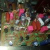
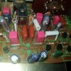
20210919_143742.jpg20210919_143747.jpg20210919_143753.jpg20210919_143803.jpg20210919_143808.jpg20210919_143814.jpg
 
Last edited:
Not the greatest picture, but I tried to get a picture of the burn spot. The spot you see at the "top" of the circled part is where the fire spark appeared. Will try and get a better picture on my new phone tomorrow.

20210920_021052.jpg
 
what I write and what you read and do don't seem to agree at times.

Remove and test (but do not replace) Q5, Q7 & Q9 if it is the left channel, or Q6, Q8 & Q10 if it is the right channel
6 way test all transistors.

and then with power on, read the voltages on pins 17 (+30v?) & 18(-30v?).

Set dmm to DC volts.
connect black dmm probe to a bare metal chassis ground
insulate all but the tiniest end of the tip of the red dmm probe
measure the voltage (touch the red probe TO) pin 17
measure the voltage (touch the red probe TO) pin 18

Of course the directions omitted stating to record which transistor came from where (my bad) for 6 way diode testing.

What replacement transistors do you have?
 
Last edited:
what I write and what you read and do don't seem to agree at times.


Set dmm to DC volts.
connect black dmm probe to a bare metal chassis ground
insulate all but the tiniest end of the tip of the red dmm probe
measure the voltage (touch the red probe TO) pin 17
measure the voltage (touch the red probe TO) pin 18

Of course the directions omitted stating to record which transistor came from where (my bad) for 6 way diode testing.

What replacement transistors do you have?

Read loud and clear, just have not had a chance to do it yet. I can see I wrote pin 7 and 8 instead of 17 and 18, stupid typo. Especially as I then mentioned soldering the wire to 17 again, straight after mentioning "pin 7 and 8".

I have 992 and 1845 transistors, although only have a couple of my "$1each 1845's" left. I thought they would get me through to the new supply but it has now been pushed back until April next year! Very frustrating.

Oh I should add, I had already replaced the transistors I mentioned before your post. I did not replace them after you said to remove and not replace and then check voltages of pin 17 and 18. I think you must have thought I replaced transistors after your message.
 
Last edited:
I removed Q5, Q7 and Q9 but could not test the voltage because the damned burn spot was back, sigh. I did not change the very slightly burnt resistors which did not spring to mind until after I tested it. My mind is... a bit screwed at the moment. I will change the 110k resistors tomorrow (well today seeing as it is after 1am) and try again!
 
Back
Top Bottom