• The move to the new server is done. There are some software and database maintenance updates in process. This has us passing the hat around to help out. We appreciate any donations. Seriously, even a dollar helps. The payment page may be found here - https://www.audiokarma.org/support.html

SA-9500 II re-cap and re-build, burnt resistor help, please?

Is the other channel working?

with those transistors out, I had expected the burning to cease. So it is something else.

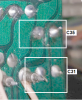
What is the status of C31? Original? Replaced? With what? Double check polarity.

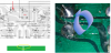
At the tip of the red arrow, there is a red line drawn on the trace, is that where the burning is happening?

upload_2021-9-20_22-53-21.png

You see the green bar graphic I drew, there are two parallel white lines that ALMOST interrupt the trace. There is only a small thin sliver of green left to conduct the current. This could be what is happening.
The fix is to strip away the green, down to the copper, up to 1/4" away to the right and left. Then the copper is tinned, and a wire laid down and soldered across the 1/2" plus length of the trace there.
These defects in the copper could be concealed by the green solder mask paint.
There are other things I would do to test during the repair process, but I do not intend to distract you from the repair
 
Is the other channel working?

with those transistors out, I had expected the burning to cease. So it is something else.

What is the status of C31? Original? Replaced? With what? Double check polarity.

At the tip of the red arrow, there is a red line drawn on the trace, is that where the burning is happening?


View attachment 2347306

You see the green bar graphic I drew, there are two parallel white lines that ALMOST interrupt the trace. There is only a small thin sliver of green left to conduct the current. This could be what is happening.
The fix is to strip away the green, down to the copper, up to 1/4" away to the right and left. Then the copper is tinned, and a wire laid down and soldered across the 1/2" plus length of the trace there.
These defects in the copper could be concealed by the green solder mask paint.
There are other things I would do to test during the repair process, but I do not intend to distract you from the repair

Thanks again, Mark!

C31, 32 and 35 are replaced with 47uf/50v caps as I could not get 35v caps when I ordered due to the shortage. Should I replace the original 35v caps?

I will try bridging the burn area tomorrow and report back.
 
a 35v to 50v increase in a capacitor's voltage rating is HARMLESS. No.

I am so frustrated by this board.... It is one step forward, 3 steps back. Bridging did not help, but solder in the hole left by the burn stopped the burning AND the relay clicked. That was without the transistors in. Once I installed Q5, 7 and 9 again, SAME RESULT!! Burnt resistors and a NEW burn hole showing up around Q7's emmitor. This also made FU1 light up and now there is no power... grrrrr!

Could there be a connection with pin 17's wire not getting enough connection and the fuse reacting? It came off again and I soldered to the base of the wire wrap on the pin. The connection is solid, but there is not a lot of wire exposed where it is soldered again.

I also realise now that I did not check the voltage of pin 17 and 18 when the transistors were out and the relay engaged. AND that I was not supposed to re-install them. Friggin hell!

I am wondering if the flux paste is responsible for the bits of copper being exposed. The board was not like that before and there is no other reason for it. Cleaning the board with cotton buds seems to pull green mask off. Just little spots along the trace edge as it was around C35 where the burn was.
 
I said NOTHING about replacing ANY transistors - be this on YOUR head.

Relay clicking is something completely new to this thread. I am going to have to re-read this thread with a gimlet eye
Coupled with not following directions and JUMPING AHEAD, you are severely testing me.

You have to realize that I have "taken over the driver's seat", and am doing the thinking, you just have to follow directions carefully.

I would have had you make some temporary connections,make some measurements, and then maybe, MAYBE install JUST Q5 and take a whole bunch more measurements.

Thing is, the pictures all seem to be doing their best to conceal, not reveal.

We are talking about the vicinity of C35, and towards C31? C31 leads are in a DIRECT line with the pin 17(+30v) and pin 18(-30v) power feeds..
c35 positive lead even looks unsoldered in the pictures.
(edit - I have to switch between two different computers if I want to analyze the pictures in depth, I have a win xp machine with photoed that allows me to stretch the gamma of a picture to tease out details that are not apparent in the posted shots)

SO, with Q5, Q7 & Q9 REMOVED, remove C35 and C31. Then clean all the flux off of that area of the board. I use acetone.

Then take pictures of that area, straight down, on both sides.

upload_2021-9-22_11-10-16.png

upload_2021-9-22_11-14-20.png
 
Last edited:
You are right, I was not thinking. Once the burning stopped and the relay clicked, I was excited thinking it was all good! Without thinking, I replaced the transistors to test it. As I said in the previous post, I completely forgot about the instructions to take the measurements for pin 17 and 18. I really do apologise, my head is not thinking straight at the moment as I have a lot **** going on. I will not mess up your instructions again, I really, really appreciate the help and really want to get this fixed. I definitely cannot afford to buy another now....

To clarify, without the transistors and the burning fixed with solder, the relay clicked in. It was obviously not clicking before as power was only being applied for 1 second. I will take the transistors out again, and replace the fuses and start again. Once the transisors are out, I will measure pin 17 and 18. I will clean the board as well. I do not have acetone at the moment, only 100% alcohol. Cannot use nail polish remover as they are all "acetone free" now here. I was planning on buying a big bottle of acetone off ebay, but did not get around to it.
 
You are not going to lose access to me if you put this to the side for a while to clear your plate (so to speak).
I need a clear head on the other end to do this right. most of my mistakes happen when I am forcing myself to do something.

If you are intent upon "doing something" - take out Q5, Q6, Q7, C31 & C35. DO NOT APPLY POWER - none of this fuse bupkus.....
It does not help to take pin 17 & Pin 18 voltages until later after we have resolved these PC board issues under the capacitors.
Especially if it is doing what I suspect it is.

Clean the board with alcohol, chip off any hardened flux that resists the alcohol.

Take and post the pictures, at your leisure.

REMEMBER, UNTIL I EXPLICITLY SAY SO, DO NOT APPLY POWER!!
 
You are not going to lose access to me if you put this to the side for a while to clear your plate (so to speak).
I need a clear head on the other end to do this right. most of my mistakes happen when I am forcing myself to do something.

If you are intent upon "doing something" - take out Q5, Q6, Q7, C31 & C35. DO NOT APPLY POWER - none of this fuse bupkus.....
It does not help to take pin 17 & Pin 18 voltages until later after we have resolved these PC board issues under the capacitors.
Especially if it is doing what I suspect it is.

Clean the board with alcohol, chip off any hardened flux that resists the alcohol.

Take and post the pictures, at your leisure.

REMEMBER, UNTIL I EXPLICITLY SAY SO, DO NOT APPLY POWER!!

Well, cannot apply power even if I wanted to, as the 800ma fuses are both dead :D Have not checked the 2amp fuses as tye switch board is not out at the moment.I will have to order them off ebay as I cannot find them locally. I have smaller 800ma fuses I bought for my AKAI GX-77 reel to reel decks. Shame I did not think to order fuses when I ordered the BOM from mouser. Can 1amp fuses be used or are fuses a verbatim number like capacitor uf? Such a noob question, embarrassed to ask. I know voltage can go up in fuses, as in caps.

I gave the board a good scrub with toothbrush and alcohol today and got rid of all the crap! Should have done this before, but I usually wait until the board is finished and amp confirmed working. Just to confirm again, the issue with the burning close to C35 seems to be okay now, after the solder "plugged" the hole which I assume allowed the current to flow again. With Q5, 7 and 9 out, the relay even clicked. I will take the photos tomorrow though. Straight above C35/31 and Q5-9. Got new desolder guns today so it will be much easier! Had to use solder wick the past fortnight.
 
:lurk: photos.

I expect that once we try to get the power flowing, that the + / - 30v regulators have been damaged, as their current draw was expected to be 4.5 milliamps.
So they put in only 2sa720 & 2sc1318 transistors, both are very low power dissipation transistors.
Blowing 800 mA fuses through them does not bode well for them.

yes, 1 amp fuses can sub for a while.

slightly more robust transistors:
512-KSA1013YBU to-92L ecb 160v 1a .9w 100mhz 160-320hfe $0.34 (R=60-120, O=100/200, Y=160/320)
512-KSC2383YTA to-92L ecb 160v 1a .9w 100mhz 160-320hfe $0.17

2sc1318 to-92 ecb 50v 0.5a 0.625W 40-340hfe 200mhz
 
Last edited:
Great, I have plenty of KSC2383YTA for the 2SC1384 and I think I may have KSA1013YBU for the 2SA720 as well. Those were not listed in the BOM I used, so I hope I am not short. I know I am short for one of the power amp replacements as they too were not on the BOM, wish I had double checked. Rather annoyed about the horrid 798 transistor on the power amps. When I tried to make those for a Sansui, they never seemed to work. But I know it needs to be replaced.
 
:lurk: photos.

I expect that once we try to get the power flowing, that the + / - 30v regulators have been damaged, as their current draw was expected to be 4.5 milliamps.
So they put in only 2sa720 & 2sc1318 transistors, both are very low power dissipation transistors.
Blowing 800 mA fuses through them does not bode well for them.

yes, 1 amp fuses can sub for a while.

slightly more robust transistors:
512-KSA1013YBU to-92L ecb 160v 1a .9w 100mhz 160-320hfe $0.34 (R=60-120, O=100/200, Y=160/320)
512-KSC2383YTA to-92L ecb 160v 1a .9w 100mhz 160-320hfe $0.17

2sc1318 to-92 ecb 50v 0.5a 0.625W 40-340hfe 200mhz

Okay! I feel like I am ready to go back to this beautiful beast to get it singing.

I took photos of the board, please let me know if they are what you require. Thank you once again in advance. :)

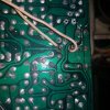
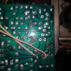
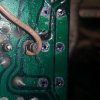
20211012_005227.jpg20211012_005227.jpg 20211012_004722.jpg20211012_004717.jpg20211012_004752.jpg
 
Ya know, there's other things in life that can demand more time investment in a particular time period, including health problems and doctor's appointments,blood draws for lab tests and etc...
I could spend HOURS trying to unravel those pictures, also figuring out which components have been removed.

put an insulated jumper between C31 MINUS terminal and Q5's emitter.
That will provide a reliable path for the -30v rail without doing a lot of fiddle pharting diagnosing and fixing the foil.

Provide a list of EXACTLY which components are NOT installed, so that I can "bless" a power-up to check the rails.
 
The first photos are of Q5,7,9 as you asked for. The second are C35,31,32 as noted in the post.

Sorry I did not say the first post was pictures of C5,7,9. I thought that it would be obvious as that is what you asked for. Thank you for your reply.
 
Last edited:
put an insulated jumper between C31 MINUS terminal and Q5's emitter.
That will provide a reliable path for the -30v rail without doing a lot of fiddle pharting diagnosing and fixing that foil.

Provide a list of EXACTLY which components are NOT installed, so that I can "bless" a power-up (After I vet the "missing" components list) to check the power supply +/- 30v low current /but can go high/ rails.


I THINK I am starting to see what went on with the failure, INCLUDING the burning 110 ohm emitter R29 & R31 resistors.
 
Last edited:
put an insulated jumper between C31 MINUS terminal and Q5's emitter.
That will provide a reliable path for the -30v rail without doing a lot of fiddle pharting diagnosing and fixing that foil.

Provide a list of EXACTLY which components are NOT installed, so that I can "bless" a power-up (After I vet the "missing" components list) to check the power supply +/- 30v low current /but can go high/ rails.


I THINK I am starting to see what went on with the failure, INCLUDING the burning 110 ohm emitter R29 & R31 resistors.

Thanks again, Mark.

Currently the Q5, Q7 and Q9 transistors are removed along with C35, C31, C32.

Should I put the insulated wire on now without the cap or transistor in? As in pad to pad? Or should I put those back in and install the wire to the legs of each?
 
Replace C31, C32 and C35. Remove Q1 & Q3
NO transistors yet.

YES, the wire is SUBSTITUTING for bad foil, the C31 minus and Q5 emitter are electrical locations,
physical locations of the wire joints will be a scraped clear area of the foil VERY near each of these components.

upload_2021-10-14_23-59-48.png

When this is ready, turn on power and measure the voltages at:
pin 17 (+30)
pin 18 (-30)
at C35 plus (+29v)
 
I re-installed the caps at C35, 31 and 32 today and took the voltages.

Pin 18 = -47.3
Pin 17 = +46.3
C35 plus = +45

Slightly on the high side but about average for what I have seen in other threads with problem amps. There was a weird sound coming from the board, may have been those 110k resistors. The relay clicked in and out a few times. Scared the **** out of me because I am so anxious about this amp, lol!

Thanks!
 
edit: BIG TEST
desolder pins 17 & 18 from the board, insulate them.
see if relay clicking stops.
see if weird sound stops.
monitor those voltages where pin 17 &18 are connected on their other ends.
-----------------------------------------------------------------------------

SO much could be going on under your nose... SMH...

Are the voltages stable (WHY is relay clicking in and out?)

Relay clicking in and out a few times? Weird sound coming from the board?

110K resistors? UNH UNH... 110 ohm resistors tolerance code K?

no.... how did you come up with a "K"??

R29, R30, R31, R32 are all carbon film 110 RD1/4PS 111J in the BOM.

RD carbon film
1/4 is a quarter watt power
PS is straight axial leads, (VS stands the resistor up with u shaped leads)
111 is 11 x (1x10) ohms = 110 ohms.
J IS GOLD, 5%
K IS SILVER, 10%
M no color 20%


111 is 11 x (1x10) ohms = 110 ohms.

110K is 100,000 ohms. BIG difference!!! 114 is 11 x (10x10x10x10) = 110,000

As far as that burning spot, I am starting to think that is trouble, and that maybe the foil should be cut on both sides of it to isolate that.
THEN see what voltages can be found on the isolated section. A rather radical step, but it's starting to look like it's needed. don't do it YET... just getting you used to the idea.
I REALLY would like some good pictures of the burned area with all the solder glop removed.

This had graduated to the difficult category.
 
Last edited:
Back
Top Bottom