• The move to the new server is done. There are some software and database maintenance updates in process. This has us passing the hat around to help out. We appreciate any donations. Seriously, even a dollar helps. The payment page may be found here - https://www.audiokarma.org/support.html

SA-9800 Frys Speakers!

ehc68 said:
One other question.....do you think this is going to solve my original issues
with this amp, or is this just going to correct what I messed up when my meter probe slipped and bring me back to the original complaint?

Well, we needed to have a good power supply before testing for amplifier problems, and the original status of the power supply is forever unknown.

Once we have the power supply nailed down, then we need to look at the DC voltages present at the amplifier outputs, BEFORE the protection relay interrupts the circuit to the speaker terminals.

But the voltages on pins 1 to 9, IF recorded BEFORE the short happened, DIDN'T look good. So the odds ARE looking better.....

Once the power supply is verified good, then you recheck for ALL the symptoms... if the protection circuit engages the speakers, still read the offsets, just do it at the speaker terminals.
 
OK....well I'll let you know when I get the transistors and when I get them installed. In the meantime, I go ahead and solder back in Q9 and Q11 since they checked out ok.
 
Sounds good to me.

As long as things behave themselves going together.

It's hard to blow up transistors when they aren't connected.

As for the problems, it's the server migration, it's giving them fits, as usual.

I say this tongue in cheek as in my software development career (embedded microprocessors) I have suffered as well:

"computers.... labor saving devices???????????? HAH..."
 
Mark, just to let you know....I ordered those transistors. I'll let you know when
they arrive and I get them soldered in. :yes:
 
I made a BIG mistake :tears: ....I ordered an Alps detector switch for a distortion pedal for a guitar which costs all of 67 cents (a real tiny little thing) and like a dummy I had it sent C.O.D. and just received a conformation email
stating it had been shipped and the shipping will be $15.46!!!
I selected the cheapest shipping option too...the USPS priority mail of $5.85.

That's one thing I don't like about Mouser. You don't know the ACTUAL shipping fees sometimes until AFTER your order is already shipped. Usually says something like "Shipping to be determined" or something like that.
 
I stick with small stuff and always specifiy first class mail.

Plus I NEVER COD... fees up the wazoo....
 
Ok...well the transistors came in today. I thought I'd go with Centerpointe because they SUPPOSEDLY had everything I needed and I figured I would save a little by only paying one shipping fee. I typed in the ORIGINAL part numbers and there was NOTHING stated about there being a cross reference to ANY of the parts. I open the package and ALL but one is cross referenced.....the 2sa733 (Q3). What REALLY pi**es me off is that the 2sk34 (Fet) is cross referenced to an NTE 459 which is a 4 lead transistor rather than 3....so it doesn't appear to even be the correct NTE replacement. I also remembered your post about staying away from NTE's and how you run the risk of them being counterfeit......well guess what? You were right!! Not that I didn't believe you, but I ended up getting stuck with it anyway.:tears:

Moral to the story....stay away from CP Electronics!!!!:nono: :thumbsdn:
 
Well, the nte459 IS a 50 volt jfet, and in this case the voltage is paramount.

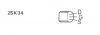
the 2sk34 is s-d-g across as drawn in the Pioneer manual

and the nte 459 is a s-d-g-(case connection) going clockwise from the tab.
so ignore that 4th lead...

Since it is in the power supply, the noise performance isn't critical,

so I would expect the other cross references to behave as well

that does NOT excuse the expectation of buying ORIGINAL parts
and getting CROSS REFERENCES.

especially if that vendor was selected with the expectation of EXACT NUMBER matches...
 
I'm a little confused on the lead arrangement. On the service manual it looked to me like 2sk34 had a lead arrangement of SGD.

The NTE looked like SDG (clockwise from tab).
 

Attachments

  • 2sk34.jpg
    2sk34.jpg
    4.6 KB · Views: 15
  • NTE459.jpg
    NTE459.jpg
    44.2 KB · Views: 23
Drat, that's 2 dyslexic screw ups since last Thursday... didn't do the customary
triple check... my bad...
 
Well....crap! I soldered them all in and the protection relay engages (as it did before), but the meter doesn't light up at all.
 
We are back to the point where we started at, (before the inadvertent slip) what are the power supply voltages, compare them to the schematic's call out?

Once the power supply voltages are correct and stable, then we check the amps and the offset control circuits.

markthefixer said:
Well, we needed to have a good power supply before testing for amplifier problems, and the original status of the power supply is forever unknown.

Once we have the power supply nailed down, then we need to look at the DC voltages present at the amplifier outputs, BEFORE the protection relay interrupts the circuit to the speaker terminals.

But the voltages on pins 1 to 9, IF recorded BEFORE the short happened, DIDN'T look good. So the odds ARE looking better.....

Once the power supply is verified good, then you recheck for ALL the symptoms... if the protection circuit engages the speakers, still read the offsets, just do it at the speaker terminals.
 
Ok.....NOW I think we're back to where we were. There was a bad solder connection on one of the transistors and now the meter works.....only when the dimmer switch is set to high, but at least it works. I was a little suspicious when it didn't work initially because it had worked before.

There are three transistors that get really hot....Q2, Q6, and Q4. Do you think they will be ok?
 
I was getting ready to check the power supply voltages, but I thought I'd better ask about those transistors first.
 
I'm not too happy with Q4 and Q6 heating up, what did we do about Q8?

WHICH transistor had the bad solder connection? That may have induced MORE problems.....

Turn it on just long enough to CAREFULLY read only these voltages:

pins.....voltage
1 or 2 -52v
3 or 4 +52v
5 or 6 +32v
10 or 11 -32v

I say or because the pins are connected together, so they will be at the same voltage

Plus, what do you mean about the meter working? The flouroscan indicator didn't light up before, or just didn't indicate... I have to look this up very carefully.
 
Well....as for what we did with Q8. That was one that never got checked, only Q1, Q3, Q7, Q9, and Q11 were pulled out and checked.

As far as what transistor had the bad solder connection, I BELIEVE it was Q5 (the JFET). I'm not 100% positive of this, however because I wasn't looking at the component side of the board, I was looking at the other side of the board when checking the connections. I was touching one meter probe on the tips of each transistor lead, then following down the board for another connection on the same circuit and touching the other probe there and checking continuity making sure each transistor was making connection to the board. Luckily all were making connection but the one transistor.

The flouroscan meter used to light up, but not evenly (some areas brighter than others), and ONLY when the dimmer switch was set to high (dimmer basically switched off). Otherwise when switch was set to low the meter wouldn't light up or indicate at all (as if the power was shut off to the unit).

NOW (after finding and correcting the bad solder connection) the flouroscan lights up nice and even, but still only illuminated when dimmer function is off.

DC Voltages at pins 1, 3, 5, and 10 are.....

1) -14.4
3) 68.6
5) 9.4
10) -10.2
 
ouch those are not good.

what are the numbers of the actual transistors sent, and what they replaced... I want to check the lead layouts for differences.

also what are the voltages on each of those transistors e, b & c (dsg) connections... especially the Q7 emitter and D5 junction.

again, first we get the positive side working... and it will improve what is happening with the meter.

we had -16.2 originally, we have -14.4 now and should have -52 on pins 1 & 2
we had +6.4 originally, we have +68.6 now and should have +52 on pins 3 & 4 this is why (+68) the meter looks better
we had +5.2 originally, we have +9.4 now and should have +32 on pins 5 & 6
we had unknown originally, we have -10.2 now and should have -32 on pins 10 & 11
 
OK....Q1, which was originally 2sc1735, was replaced by 2sc1627.

Q3, which was originally 2sa733, was replaced by one of the same.

Q5, which was originally 2sk34, was replaced by NTE459. These lead layouts were different, but soldered in accordingly.

Q7, which was originally 2sc1914, was replaced by 2sc2631.

I'll get back with you tomorrow with the transistor voltages.
 
I was getting ready to check voltages on the transistors, but I guess I better wait until we get the lead layouts to make sure they are correct first just in case that is what's causing Q2, Q6, and Q4 to heat up.....right?

I was just thinking that IF this is what's causing them to heat up, then after I switch the leads around I would be able to check the voltages without running the risk of frying the transistors or whatever else.
Just a thought....your the man so if you want me to check them now, I'll check them now!:D
 
AAAAAAAAAARRRRRRRRRRRRRRRRGGGGGGGGGGGGGGGGGHHHHHHHHHHHHH!!!!!!

We both dropped the ball on this one. me 75% you 25%

I should have looked them up when the substitutions were first detected.
or
I should have told you to test them with the diode test
or
I should have told you to look them up

Plus it's one of EchoWars mantras ..... use the diode test to be SURE of the lead arrangement...

When I physically do transistor replacements I ALWAYS always ALWAYS verify the board connect positions, the old devices layout, the supposed layout of the new device, it's supposed new orientation on the board and I TEST the damn thing to be sure they didn't send me a bad one...

It takes me less time to do that than to unravel NEW faults...

The originals, the 2sc1735 and 2sc1914 have a B - C - E layout according to the Pioneer manual

the replacements, the 2sc1627 and 2sc2631 have E - C - B layouts, exactly the OPPOSITE!!!

Pull them out (q1,q3,q7), TEST all of them while they are out of circuit to see if we zapped any of them...and if ok, put them in right.

Then re-check the 4 power supply voltages (+/- 52, +/- 32 ).

If the 4 power supply voltages are within 10 to 20 percent of their assigned value, don't bother reading the transistor voltages. If any of the power supply voltages are incorrect, read these transistors for the incorrect voltage(s).
If the +52 is incorrect, don't bother with any of the other transistor supply's voltages.
IF the bigger voltage is incorrect, don't bother with the lower voltage of that polarity.
This is the rough order of priority... :

+52 (on pins 3 & 4) is q1,q3,q7
+32 (on pins 5 & 6) is q9,q11

-52 (on pins 1 & 2) is q2,q4,q8
-32 (on pins 10 & 11) is q10,q12

I reviewed the thread and any PM's and we didn't do anything about replacing Q9 and Q11, correct?

 
Back
Top Bottom