• The move to the new server is done. There are some software and database maintenance updates in process. This has us passing the hat around to help out. We appreciate any donations. Seriously, even a dollar helps. The payment page may be found here - https://www.audiokarma.org/support.html

SA-9800 Re-Work Begins

I hate to sound really lazy, but do you have a complete list of the parts that you ordered. I know I could go through this thread (and others) and see what's needed, but some of us are also on limited posting time as well.

It would really be a great help.

Lee.

Yes. But as always... take this parts list with caution and ALWAYS, ALWAYS look at your very own SA-9800 to check the validity of this list to what you actually have in your unit, because they can AND DO often vary. And, THIS particular list is mine and for my specific SA-9800 and my situation. And one final word of caution... this list may have been modified a tad for the order placed, to be used as a guide only. YMMV... Good luck.

Capacitors

Power Supply
awr-194 c2 220uf 80v ceb axial 220 100 647-TVX2A221MCD
awr-194 c3 220uf 80v ceb axial 220 100 647-TVX2A221MCD
awr-194 c4 47uf 10v cea 47 10 647-UPW1A470MDD6
awr-194 c7 47uf 63v cea 47 100 647-UPW2A470MPD1TD
awr-194 c8 47uf 63v cea 47 100 647-UPW2A470MPD1TD
awr-194 c9 47uf 63v cea 47 100 647-UPW2A470MPD1TD
awr-194 c10 47uf 63v cea 47 100 647-UPW2A470MPD1TD
awr-194 c13 2.2uf 50v cea 2.2 50 647-UPW1H2R2MDD
awr-194 c14 2.2uf 50v cea 2.2 50 647-UPW1H2R2MDD
awr-194 c15 100uf 35v cea 100 35 647-UPW1V101MPD1TD
awr-194 c16 100uf 35v cea 100 35 647-UPW1V101MPD1TD
awr-194 c17 10uf 80v cea 10 100 647-UPW2A100MED

Amp Left
gwh-129 c1 2.2uf 50v ceanl 2.2 50 647-UKL1H2R2MDDANA
gwh-129 c11 47uf 63v cea 47 100 647-UPW2A470MPD1TD
gwh-129 c13 47uf 63v cea 47 100 647-UPW2A470MPD1TD

Amp Right
gwh-130 c2 2.2uf 50v ceanl 2.2 50 647-UKL1H2R2MDDANA
gwh-130 c12 47uf 63v cea 47 100 647-UPW2A470MPD1TD
gwh-130 c14 47uf 63v cea 47 100 647-UPW2A470MPD1TD

EQ
gwf-116 c3 100uf 6v ceanl 100 10 647-UKL1A101KED1TD
gwf-116 c4 100uf 6v ceanl 100 10 647-UKL1A101KED1TD
gwf-116 c5 100uf 6v ceanl 100 10 647-UKL1A101KED1TD
gwf-116 c6 100uf 6v ceanl 100 10 647-UKL1A101KED1TD
gwf-116 c7 100uf 6v ceanl 100 10 647-UKL1A101KED1TD
gwf-116 c8 100uf 6v ceanl 100 10 647-UKL1A101KED1TD
gwf-116 c9 100uf 35v cea 100 35 647-UPW1V101MPD1TD
gwf-116 c10 100uf 35v cea 100 35 647-UPW1V101MPD1TD
gwf-116 c11 100uf 35v cea 100 35 647-UPW1V101MPD1TD
gwf-116 c12 100uf 35v cea 100 35 647-UPW1V101MPD1TD
gwf-116 c17 100uf 16v cea 100 16 647-UPW1C101MED
gwf-116 c18 100uf 16v cea 100 16 647-UPW1C101MED
gwf-116 c19 100uf 16v cea 100 16 647-UPW1C101MED
gwf-116 c20 100uf 16v cea 100 16 647-UPW1C101MED
gwf-116 c23 4.7uf 25v ach-318 np 4.7 25 647-UES1E4R7MDM
gwf-116 c24 4.7uf 25v ach-318 np 4.7 25 647-UES1E4R7MDM
gwf-116 c35 220uf 10v cea 220 10 647-UPW1A221MED
gwf-116 c36 220uf 10v cea 220 10 647-UPW1A221MED
gwf-116 c41 4.7uf 25v ach-318 np 4.7 25 647-UES1E4R7MDM
gwf-116 c42 4.7uf 25v ach-318 np 4.7 25 647-UES1E4R7MDM
gwf-116 c45 47uf 50v cea 47 50 647-UPW1H470MED
gwf-116 c46 47uf 50v cea 47 50 647-UPW1H470MED

Protection
awm-163 c1 470uf 6v cea 470 10 647-UPW1A471MPD
awm-163 c2 220uf 16v cea 220 25 647-UPW1E221MPD
awm-163 c3 4.7uf 50v cea 4.7 50 647-UPW1H4R7MDD

Filter
gws-176 c39 1uf 50v ceanl 1 50 647-UKL1H010MDDANA
gws-176 c40 1uf 50v ceanl 1 50 647-UKL1H010MDDANA
gws-176 c41 2.2uf 50v ceanl 2.2 50 647-UKL1H2R2MDDANA
gws-176 c42 2.2uf 50v ceanl 2.2 50 647-UKL1H2R2MDDANA

TC
gwg-124 c7 4.7uf 25v ach-318 np 4.7 25 647-UES1E4R7MDM
gwg-124 c8 4.7uf 25v ach-318 np 4.7 25 647-UES1E4R7MDM
gwg-124 c19 10uf 16v ceanl 10 16 647-UKL1C100KDDANA
gwg-124 c20 10uf 16v ceanl 10 16 647-UKL1C100KDDANA
gwg-124 c29 4.7uf 25v ceanl 4.7 25 647-UKL1E4R7KDDANA
gwg-124 c30 4.7uf 25v ceanl 4.7 25 647-UKL1E4R7KDDANA
gwg-124 c31 47uf 35v cea 47 35 647-UPW1V470MED
gwg-124 c32 47uf 35v cea 47 35 647-UPW1V470MED

Indicator
awv-002 c3 1uf 50v cea 1 50 647-UPW1H010MDD1TD
awv-002 c4 1uf 50v cea 1 50 647-UPW1H010MDD1TD
awv-002 c5 2.2uf 50v cea 2.2 50 647-UPW1H2R2MDD
awv-002 c6 2.2uf 50v cea 2.2 50 647-UPW1H2R2MDD
awv-002 c9 47uf 10v cea 47 10 647-UPW1A470MDD6
awv-002 c10 220uf 25v cea 220 25 647-UPW1E221MPD
awv-002 c11 3.3uf 50v cea 3.3 100 647-UPW2A3R3MDD
awv-002 c12 3.3uf 50v cea 3.3 100 647-UPW2A3R3MDD


Trim Pots

Amp Left
gwh-129 vr1 330k multi offset 652-3296P-1-204LF
gwh-129 vr3 100 single idle 70 652-3386H-1-101LF
gwh-129 vr5 47k single idle 56 652-3386H-1-503LF

Amp Right
gwh-130 vr2 330k multi offset 652-3296P-1-204LF
gwh-130 vr4 100 single idle 70 652-3386H-1-101LF
gwh-130 vr6 47k single idle 56 652-3386H-1-503LF


Transistors

Power Supply
awr-194 q1 2sc1735 pwr pass + 100v .5a .8w 512-KSC2690AYS to-126
awr-194 q2 2sc1735 pwr pass - 100v .5a .8w 512-KSC2690AYS to-126
awr-194 q3 2sa733 pwr darl + 50v 0.15a 0.25w 512-KSA1013YBU to-92L
awr-194 q4 2sa904 pwr darl - 90v 0.05a 0.2w 512-KSA1013YBU to-92L
awr-194 q5 2sk34
awr-194 q6 2sk34
awr-194 q7 2sc1914 fb ampl + 90v 0.05a 0.2w 512-KSC1845FTA (ln)to-92
awr-194 q8 2sa904 fb ampl - 90v 0.05a 0.2w 512-KSA992FBU (ln)to-92
awr-194 q9 2sc945 lv err amp + 50v 0.1a 0.25w 512-KSC2383YBU to-92L
awr-194 q10 2sa733 lv err amp - 50v 0.15a 0.25w 512-KSA1013YBU to-92L
awr-194 q11 2sd712 Replace with 512-KSC2073TU
awr-194 q12 2sb682 Replace with 512-KSA940TU
awr-194 d5 xz-060 main zener 512-1n5233b
awr-194 d10 mz-177 512-1N5247B

Protection Board
awm-163 Q1 2SC945A Replace with 512-KSC2383OTA
awm-163 Q2 2SC945A Replace with 512-KSC2383OTA
awm-163 Q3 2SC1885 Replace with 512-KSC2690AYS to-126

Amp Left
gwh-129 Q7 2SA912 TO-92L Replace with 512-KSA1220AYS TO-126
gwh-129 Q9 2SA726S Replace with 512-KSA992FBU
gwh-129 Q11 2SC1885 TO-92L Replace with 512-KSC2690AYS TO-126

Amp Right
gwh-130 Q8 2SA912 TO-92L Replace with 512-KSA1220AYS TO-126
gwh-130 Q10 2SA726S Replace with 512-KSA992FBU
gwh-130 Q12 2SC1885 TO-92L Replace with 512-KSC2690AYS TO-126
 
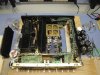
Parts in from Mouser. Started with the Power Supply board. Pretty much shotgun. Replaced all electrolytics and all transistors. 12 caps, 12 transistors and 2 diodes in total on that board. What a biatch to get to some of those without disconnecting any wires... Was able to tilt the board out only about 45 degrees or so (after removing the 6 screws). All the other boards will be significantly easier no doubt.

Used 2SK30A-Y transistors in place of the two SK34's (Q5 & Q6)

Had some solder pad issues/trace lifts on the two transistors with the heat-sinks (Q11 & Q12). Excessive heat/cooldowns I presume... Was able to doctor them up and get them in place with new thermal paste and snug mounting.

Went ahead and powered it up afterward and everything functions well (still).:yes:

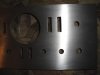
ON A SIDE NOTE: Been working with the faceplate too. Have a COMPLETE design layout of all cutouts and markings in the Front Panel Design software (took about 7 hours total over 3 nights). Everything lined up to within 0.5mm. Took off all the plastic pieces around the switch slots and flouroscan meter window and I am going to sand it down completely (has some significant scratches). Then I'm going to send it away to the Front Panel Express guys for etching. Should turn out real nice. I might polish the face, or possibly do the brushed finish like I did on my SA-9100.

Just wanted to update the thread for those that are following it.

Slowly but surely:boink:
 

Attachments

  • DSC00082.jpg
    DSC00082.jpg
    61.2 KB · Views: 188
  • 9800 Faceplate.jpg
    9800 Faceplate.jpg
    68.8 KB · Views: 133
Last edited:
Used 2SK30A-Y transistors in place of the two SK34's (Q5 & Q6)

Reason for the switch? Out of stock?

Getting ready to dive into my power board. Multiple visibly bad caps and scorching eerily similiar to your pics. Just got done visually confirming the transistors and getting ready to compare the caps to your list. Worth mentioning that my AWR-191-A power supply assembly appears to be identical to your 194 thus far.

Keep up the good work and keep us updated.
 
Sk30 as the sk34 are unobtanium and these are a suitable replacement in that circuit. The sk30 is very difficult to find, if not unobtanium as well.

I am done with the entire power supply board and the eq board. Just plugging away at it as I have time.
 
Hi Brent,

I don't want to hijack your thread with my own 9800 problems/restoration, I will start my own once I get into it seriously. But I brought the old thing up from the holding area (basement) to the workbench (kitchen table) after everyone had gone to bed, and took some measurements. The results are interesting to say the least...

4 fuses on PSU board all good. Amp power light comes on, protection relay clicks after 5 seconds, no display. I was assuming I should measure from the pins listed to a suitable ground (like pin 8). I have added the voltages I got to your measurements below in red.

pins 1&2: -53v, -6.2v, should be -52v, regulated
pins 3&4: +53v, +4.2v, should be +52v, regulated
pins 5&6: +32v, -0.3v, should be +32v, regulated
pin 7: +19v, -0.3v, should be +18v, regulated, provides power for display circuit
pin 8: 0v, ground
pin 9: -50v, raw, -75.3v, unregulated
pins 10&11: -32v, -0.2v, should be -32v, regulated
pin 12: +49v, raw, +74.6v, unregulated
pin 13: +69v, raw, +74.6v, unregulated
pin 14: 0v, ground
pin 15: -70v, raw, -75.5v, unregulated
pin 16: +6.7vac, +6.6vac, this is an AC voltage
pin 17: +53.4vac, +56.6vac, this is an AC voltage
pin 18: +53.7vac, +56.5vac, this is an AC voltage

Looks like mine is losing power somewhere. There was a red 2.2k resistor, I believe it was R5, that was getting hot.

Lee.
 
Yeah. I see you have some voltage concerns there. I would start your own thread and see if one of the experts can help you out with what might be happening.

I was able to get the right amp board recapped, transistors replaced and the 3 pots swapped out. Also pulled the 4 main caps and cleaned up the board for installation of the new main caps.

Nothing too interesting to note at this stage, other than the de-soldering of the main caps takes a special technique to suck/wick away the solder freeing up the pins so the caps can be maneuvered out successfully. Took all the power my little Weller iron had to offer.
 

Attachments

  • DSC00182.jpg
    DSC00182.jpg
    103.8 KB · Views: 175
Last edited:
All 4 main caps replaced. The right channel power amp board is all done and the output transistors on that side have been re-thermal pasted and put back on. The 2 heat sinked power amp board transistors (913's) were cleaned and new thermal paste applied. Also reflowed solder over those transistors and inspected all solder joints on the right PA board. All of the right channel is completely reworked and buttoned back up. Now to the left power amp board. Moving right along.
 
The right channel power amp board is now done. Found R89 and R90 resistors were burned and open. They are 10 ohm 1 watt, flameproof. I replaced both with new ones. Although the amp worked well with these open.

Just have a few more smaller boards to recap and 3 transistors on the protection board and it'll be ready for the DBT start up. :yes:
 
those 10 ohm resistors are in series with 0.047uf caps to ground on the outputs, think of the frequency necessary to pass enough wattage to hurt the resistor...
all is not well.
 
Last edited:
those 10 ohm resistors are in series with 0.047uf caps to ground on the outputs, think of the frequency necessary to pass enough wattage to hurt the resistor...
all is not well.

So do you think I need to check/test some other components while in there and it is opened up? All of the El Caps have been replaced, as well as all of the transistors mentioned in this thread and amp board trim pots. I know all of my voltages were decent prior to beginning the rework. Are those 10 ohm resistors a sign of trouble, or looming issues?

Other cap types do not need replacement.

trim pots, sigh.... :sigh:

gwh-129 vr1 330k multi offset 652-3296P-1-204LF
gwh-129 vr3 100 single idle 70 652-3386H-1-101LF
gwh-129 vr5 47k single idle 56 652-3386H-1-503LF

gwh-130 vr2 330k multi offset 652-3296P-1-204LF
gwh-130 vr4 100 single idle 70 652-3386H-1-101LF
gwh-130 vr6 47k single idle 56 652-3386H-1-503LF

Couple of questions... You show VR5 and VR6 as 47k but they are actually 68k. The replacements you spec'd out are 50k (18k difference on the low side). Is this what you intended? Want to make sure before I power it up. In looking at the Bourns single turn pots it is either 50k or 100k, no in between it appears. Just wanted to double check that they shouldn't be 100k pots. Looks like you indicated those due to availability, and that they will perform fine, but better safe than sorry, especially for the balancing on this non-switching behemoth.

Also the 330k have been replaced with 200k. I figure this is fine, but wanted to verify. Can you please confirm these?
 
Last edited:
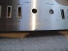
And in the spirit of the rework, I have been working on the faceplate. I have been in coordination with the folks over at Front Panel Express and have the detailed design done for etching and infill of the entire faceplate. Once I have it prepped, I will send it over and have it back within about a week. Here are some photos as of this evenings progress. Hand sanding with a hard flat block with 150 grain to remove the lettering and outer finish (anodizing?). It is raw now and needs progressively finer paper and wet sanding. I am torn between polishing it out to a shine or re-surfacing it with the brushed look as I did on my SA-9100.
 

Attachments

  • DSC00009.jpg
    DSC00009.jpg
    60.4 KB · Views: 149
  • DSC00012.jpg
    DSC00012.jpg
    64.4 KB · Views: 130
  • DSC00013.jpg
    DSC00013.jpg
    61.9 KB · Views: 124
Last edited:
Yeah. I see you have some voltage concerns there. I would start your own thread and see if one of the experts can help you out with what might be happening.

OK, I started up my own thread here so I don't have to keep commenting on yours. Hopefully, the same useful people will check it out and guide me along.

I got some interesting voltages probing around on the power supply, including 165v AC across an 80v electrolytic capacitor...

Lee.
 
All 4 main caps replaced. The right channel power amp board is all done and the output transistors on that side have been re-thermal pasted and put back on. The 2 heat sinked power amp board transistors (913's) were cleaned and new thermal paste applied. Also reflowed solder over those transistors and inspected all solder joints on the right PA board. All of the right channel is completely reworked and buttoned back up. Now to the left power amp board. Moving right along.

Do those output transistors you re-assembled with new paste have mica thermal washers or something similar? Just curious.
 
Yes. They are pretty fragile. But removal with a fresh razor blade and then cleaning with a cloth lying on a hard flat surface works well. They are difficult to find this particular size/shape. You could always use a product called Silpad. Avail at Mouser.
 
Back
Top Bottom