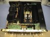
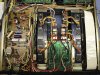
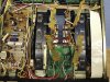
Just thought I would post a few pictures of where the internal work sits as of today. I also went ahead and replaced the output transistors with On-Semi MJL3281 and MJL1302. As you can see in the photos, there was quite a bit of modification done to make this work. I was going to go with the "Phoenix" type connectors, but opted against it and went with direct soldering straight from the Amp boards. It turned out well.
Other than this mod, it went well and pretty smooth. The amp sounds really nice and smooth.
Also, to help out fellow AK'rs, I am going to post some of MY voltages below so if anyone might want to take a look at what I have as references for a working unit, they will be memorialized here in one single post. If 2 voltages are shown, the first voltage is the "expected" voltage and the one to the right of that is my actual voltage. Just keep in mind that these are not gospel, but to simply give a reference as I know there are quite a few people working on SA-9800 amps watching this thread, and hopefully in the future this might help others out as well. Also keep in mind that the voltage reading may have fluctuated a bit as the unit continued to warm up as the voltages were taken, hence a bit higher readings on the Power Amp Left board as compared to the Right side.
AWR-194 (Power Supply Assy)
pins 1&2: -52v regulated, -52v
pins 3&4: +52v regulated, +52v
pins 5&6: +32v regulated, +32v
pin 7: +18v regulated, +18v (provides power for display circuit)
pin 8: 0v, ground
pin 9: -50v, raw, unregulated
pins 10&11: -32v regulated, -32v
pin 12: +49v unregulated raw
pin 13: +69v unregulated raw
pin 14: 0v, ground
pin 15: -70v unregulated raw
pin 16: +6.7vac, this is an AC voltage
pin 17: +53.4vac, this is an AC voltage
pin 18: +53.7vac, this is an AC voltage
GWH-130 Power Amp (Right)
pin 3 +52v: +52v
pin 4 -52v: -52v
pin 7 -50 to -55v: -55v
pin 15 +50 to +55v: +55v
Voltages driving the transistors:
pin 8 -0.592v
pin 14 +0.601v
pin 11 0v: 0v
The emitter voltages:
pin 9: -34.0mv
pin 10: -34.8mv
pin 12: +33.1mv
pin 13: +32.4mv
Idle current measured between pins 18(+) and 20(-): +70.0mv (Thanks to the new single-turn Bourns pot)
GWH-129 Power Amp (Left)
pin 34 +52v: +52v
pin 33 -52v: -52v
pin 30 -50 to -55v: -55v
pin 22 +50 to +55v: +55v
Voltages driving the transistors:
pin 23 +0.592v
pin 29 -0.583v
pin 26 0v: 0v
The emitter voltages:
pin 24: +36.2mv
pin 25: +35.2mv
pin 27: -34.0mv
pin 28: -33.2mv
Idle current measured between pins 39(+) to pin 37(-): +70.0mv (Thanks to the new single-turn Bourns pot)
Rectifier board:
pin 16: +55v
pin 17: -55v
pin 13: -55v
pin 14 : +55v




 j/k.
j/k.