• The move to the new server is done. There are some software and database maintenance updates in process. This has us passing the hat around to help out. We appreciate any donations. Seriously, even a dollar helps. The payment page may be found here - https://www.audiokarma.org/support.html

Sabotage of KA-7100?

Changing rectifiers is a bone of contention. If your rectifiers test OK, then there is no reason to change them. However, if you are planning on making your main filter caps larger as myself and others have done, then you might want to consider new components. Mouser still has 1N5404 diodes in stock right now. That situation might change, although I don't really see people panic buying diodes.

My 2 cents.
 
Changing rectifiers is a bone of contention. If your rectifiers test OK, then there is no reason to change them. However, if you are planning on making your main filter caps larger as myself and others have done, then you might want to consider new components. Mouser still has 1N5404 diodes in stock right now. That situation might change, although I don't really see people panic buying diodes.

My 2 cents.

Thanks, Lee. However, I noticed your post immediately after placing an order for parts including the standard main filter caps. Is durability the reason for the larger caps you opted for?

On the subject of rectifiers, I'm assuming that multimeter diode test values of 5.00 to 5.50 are just fine. If I'm wrong about that, please shout.

When the parts arrive, we'll be replacing the output transistors. Hoping that solves the short circuit that blew the fuses. :yikes:

Also a shout out of thanks to avionic and rickl for their recent suggestions.
 
Got some parts in and here's where we are now:
  1. Replaced all 4 output transistors after testing and finding 3 of them bad. It worked to power on the amp without blowing fuses but only the left channel produced any sound irrespective of input source. Tried hooking up to both sets of speaker terminals - right is quiet on both. Also tried headphones. Same issue.
  2. Replaced the fusible resistors at Re75-Re78
  3. Checked regulated power supply per your video and measured the positive terminal at +33 and negative at -12. If this suggests replacement of components, which would we replace?
  4. Decided to check the DC Offsets. Left produced 30mV but right measured nothing at all, even after trying to adjust using the trim pot. I understand the DC offsets should be at 20mV and are adjustable.
Would welcome your advice on what to try next to get sound out of the right channel.
 
If your -B is -12v, you need to find and fix that. Here is the PS with some factory voltages. yours might be a little lower if you are using a DBT.

upload_2022-4-20_14-48-17.png

post your measurements.
 
Last edited:
Voltages (without DBT)
Schematic (V) / Actual (V)

-47 / -45.2
-42 / -14.3
-28.5 / -14.3
+47 / +45.4
-28 (Pin 7) / -13.6
+28 (Pin 8) / +35.9 <-----not asked for but reported because of difference from schematic.
 
i'd probably rummage through my parts bin and find a 28v zener and see if swapping it for De18 did anything. Or verify Qe32 is working.
 
Sadly I have no parts bin (although starting to build one). So, ordering a few zeners and picking up equivalents of the two power transistors at the same time. $10 shipping is more than 2X the cost of the parts. I'll report back after replacing the 28V zener.
 
Hello Rickl and other AudioKarma members.

Replaced the zener (D18) with a 28v unit but still no sound and MM not providing all the right readings.

Replaced the transistor (Q32) and all the relevant readings from Rickl's questions came up to proper voltages. However, still no sound from the right channel.

Tried adjusting the center channel bias (VR1 and VR2). On VR1 (left channel) was able to bring reading to 0. On VR2 (right channel) could only adjust between 12.0 - 13.5mV.

Tried adjusting VR3 (left channel) and VR4 (right channel). VR3 adjusted to 20.0. VR4, however, would not move off of 19.9V when turned to right and left stops of pot.

Suggestions where to look next?
 
Had time to replace some components and take a bunch of measurements. Still no audio signal on the Right channel.

Key components replaced include:
  • Transistors Qe31 & Qe32
  • Diodes De17 & De18
  • Capacitors Ce29 & Ce30 (470uF 50V)
  • (4) Capacitors Ce31-Ce34 (6800uF 63V in place of original 50V)

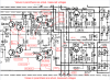
Diagram (provided as image file and as a PDF) shows specified values and the actual measured values (shown in parentheses). Have measured additional voltage values back to, but not including, the FETs (Qe1 and Qe2) and can post those values upon request.

Would be very grateful for guidance on how to get key values at or close to spec and / or any further diagnostic steps to take in order to pinpoint faulty components.
 

Attachments

Last edited:
I didn't look at your attachments but there are a couple things you can do to narrow down the problem.

Inject a signal at the volume pot to see if the power amp is good.

I think there is a tone bypass to see if the tone stack is good.

Inject a the aux in and check level at volume pot. If only one channel working, Do it again using tuner input. If still bad try the tone switch.

This assumes all switches and pots are clean and working.

Post results.
 
Looked at your measurements - the issue is probably before the output stage. Need voltages from Qe2 to Qe12.
Wild guess - Re40 (120 ohm)
 
Hey, guys. I've been gone on extended travel but Collin and I had some time this weekend to devote to the KA-7100.

Inject a signal at the volume pot to see if the power amp is good.

I think there is a tone bypass to see if the tone stack is good.

Inject a the aux in and check level at volume pot. If only one channel working, Do it again using tuner input. If still bad try the tone switch.

Not sure we fully understand your suggestions, Rickl, and whether or not they require special equipment - a tone generator?; something to measure the output level? Sorry, newbies here with limited gear and familiarity with jargon.


Looked at your measurements - the issue is probably before the output stage. Need voltages from Qe2 to Qe12.
Wild guess - Re40 (120 ohm)

Re40 measures at 120 ohms. Was hoping your guess was right.

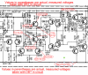
Values from Qe2 to Qe30 are attached (as image and as PDF) so we hope the super-sleuths among you can tell us where to look next.

Thanks again for your continued attention and advice, amigos.
 

Attachments

Values from Qe2 to Qe30 are attached (as image and as PDF) so we hope the super-sleuths among you can tell us where to look next.

Thanks again for your continued attention and advice, amigos.

Two things jump out. First, voltage drops across R44 and R46 (both 270 ohms). Those resistors should be red hot if so, and are probably open.
Not as important, but some of the voltages are negative and not labeled as such. The voltage rail on top is the negative rail (dotted line -45 or so) and the =45 is at the bottom, and the ground is just below the negative rail, which does make things confusing.
Keep it on a DBT - if those resistors are open, there may be other issues when replaced. My guess is that they went when outputs went.
 
Last edited:
Hey, Steve - you were right that those two resistors were open and non-functional. I got 270 ohm resistors delivered today and expect to have two of them soldered in the R44 and R46 positions this weekend.

Once installed, I'll power up through a DBT. Question is: If the DBT glows and then dims, should I go ahead and hook up an audio source and check the faulty right channel for output while still powered up through the DBT? If so, should I expect fairly low volume (assuming that channel now is working)?

Or, if the DBT glows and then dims, should I consider it safe to take the DBT out of play and plug directly into the wall to see if audio is present in the right channel?
 
I'd check some voltages while on the DBT. If nothing looks too far out of line, then try audio on DBT. If relay clicks, gain should be okay, it should distort at lower volumes. I hope.
 
Replaced the two resistors. Powered on through a DBT which glowed momentarily and then went very dim (100W bulb). However, the relay did not click as it has been doing prior to replacing the resistors.

Since the relay did not close and I did not take the DBT out of the equation, either, I did not spend much time checking voltages as I figured they would not read in any realistic way.

Any idea where to go from here?
 
Check voltages. Even with DBT they can give useful info. Rail voltages (easiest to get from the cases of the output transistors) (for reference), output (easiest to get from emitter resistors), and voltages around Qe10, 12 and 14 for directions to go.
 
Rail values and Qe10, Qe12, Qe14 values as well (in PDF and PNG formats). Measured after replacing resistors Re44 & Re46. Note that the values were measured with a DBT in place / protection relay not clicking.
 

Attachments

Back
Top Bottom