What are the voltage ratings of those caps on your board?



Could have been a tiny spec of something or maybe a tiny flaw. Obviously tiny since it took full power to break through.I pulled the output module apart. I thoroughly checked the output board, driver boards and relay boards, component by component with no visible signs of any problems, carbon, arcing etc. I pulled the bias transistors which did not test in-circuit and checked them out of circuit and they tested fine.
I checked every diode and resistor, and the driver transistors for shorts, on both drive boards and the relay board -- no detectable issues. No visible problems. I did not pull any transistors from the drive boards, but did test for shorts.
THEN . . . I saw it.
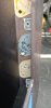
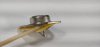
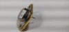
I had checked the outputs before I pulled them from the heat sinks and they all tested fine. But I decided to test them now that they were removed from the heat sink. Then I saw a tiny black spot on the edge of one of the 2SD424s - the one next to the one that shorted. The case (collector) shorted to the heat sink and made a hole in the silpad, and made a tiny arc hole on the edge of the transistor package, and the heat sink, where it left a carbon flash. See photos.
Could the failed component be the silpad in both the internally and externally shorted transistors? Could excessive current have caused the silpad to fail? If so what may have caused the excessive current. I was monitoring bias, and QC when it went, and they were right where they should be. I still have not found any evidence of what else could have caused the failures.
This is my first time using silpads. Could they be too "thin" or otherwise defective? Did I use the wrong type (see last photo)? Could I have installed them incorrectly? Seems pretty simple. Put the silpad on the clean heatsink, install the transistor, carefully tighten screws. No I don't have a torque screwdriver, but was careful to use my finger tips to turn the screwdriver, and alternate across the screws and not over tighten.
I think that when I put it back together, despite the convenience of the silpads, I will use mica insulators and paste. Even though the transistor that burned through the silpad tested OK, I don't plan on reusing it.
For the relay release, I removed the jumper from the output board. Instead of running the new wire (from the AC side of the bridge rectifier) to the board and cutting the trace, I added a small piece of perf board and mounted the diode on it and used it as a tie point for the feed wire, which connects to the anode of a 4N4004. The cathode is connected to the pin (two actually) that was fed by the jumper, and the new cap (+). The (-) side of the cap is soldered to a lug that replaced a lock washer in the hardware that connects the heat sink to the board. While physically different from they way Craig described it, I think it is the same electrically. The relay was cutting out immediately on power down while the amp was functioning properly. I did notice that during both shorting events, the relays clicked, but I was reaching for the off switch and did not notice if they cut out and stayed out. They did not kill the power - but don't think they were designed to do that.