• The move to the new server is done. There are some software and database maintenance updates in process. This has us passing the hat around to help out. We appreciate any donations. Seriously, even a dollar helps. The payment page may be found here - https://www.audiokarma.org/support.html

SAE 2400L Restoration

Ah yes. The brown is the center tap of the secondary. When I pulled it off the cap/ground, secondary was no longer connected to ground. I then pulled the output module up to see if perhaps I pinched a wire or if there were any shorts there, but found nothing.
 
Resumed diagnostics this AM. Isolated the Line in and DC cap wiring and checked for shorts between legs and to ground, and found nothing. Put things back together one thing at a time and checked with DBT before adding in the next thing in the circuit. With everything in place except the drive boards, the DBT bub stays dim, fan runs, relays click in. When I put a drive board (either one) into channel A, the bulb gets bright. This does not happen when I put a board into channel B only. Since both boards check out OK in slot B, but I get a bright bulb with either board in CH A, I presume it is not something related to the drive board(s). The relays did not click in when there was a board only in B. With a board only in A, or A and B, I don't think the relay clicked in, but I turned it off pretty quickly, so not sure if it would have not not. These tests were made with nothing connected to the inputs or outputs.

I assume I have ruled out the AC wiring, power switch, thermal switch, fan, transformer, rectifier, DC wiring to caps, and maybe the DC wiring from the caps to the output board.
This leads me to suspect something in the A channel only on the output board. When I had the output module apart, I checked the board for shorts, bad components etc, but there must be something lurking there. At least this gives me an area to focus on for further digging. I'll probably start with the output transistors (again).
 
I removed (physically) the output module, but kept it wired in to the power supply and properly grounded to the chassis and did a bunch of checks.
- Checked all 8 output transistors without removing them, I connected leads from a DCA55 to the corresponding pins in the output board. All checked fine. I also verified that they are installed in the correct positions.
- Checked with an ohm meter (set to audible continuity) between each lead of all outputs and each other, and ground - no beeps.
- I then put the drive boards back into the output module, and checked and logged resistance readings from each pin on the 15-pin molex to each of the other pins and to ground. I did this for each board. There were no significant differences between the readings on board in the A position or the board in the B position.

I'm still trying to think of things to check, but something is causing the 200W DBT to go bright when there is a board in the A slot.

Any ideas @llwhtt, @hamrules, or anyone else?
 
Check the header for a solder joint touching another maybe.
I've been reading over what you wrote about the mod to disengage the relays on power down. I am wondering if not cutting the trace is causing the issue. My pics I have saved from my repair job are not good but it looks like it might connect into the "A" channel header somewhere, IDK. As I said my pics are real bad and I can’t follow the traces worth a hooty. Just bringing it up just in case.
 
Last edited:
Ham,
When you say check the header, what are you referring to? The molex connectors or something else? I have not checked the molex connectors between the output board and the relay board, I should.

I had this thing working without this problem, it is only since the transistors blew and I took it apart and put it back together, but in that process, I guess anything could have happened. That is why I did all those checks with the ohm meter on the output board to drive board molex connectors.

Regarding the power down mod, I'm pretty sure once I removed the jumper and did not insert the AC power wire (as per Craig's mod) that the trace is only connected to the two pins that go to the relay board. It is definitely worth double checking to make sure that trace does not go anywhere else - but I'm pretty sure I did that (visually and with an ohm/continuity meter) before deciding to execute the mod the way I did. The trace is energized with about 50v DC (output of the diode/cap power supply) from its connection to the relay board pins and then along the trace to the point where the jumper was removed - I don't think it goes anywhere else. Also, it was working great with this mod in place for several hours over several days of testing before the transistors went kerflooey.
 
I couldn’t follow on my crummy pics I had, just wanted to make sure is all.
Yes the molex connector pins, just a double check.
You know how that goes when you take stuff apart and back together.
 
I'm still trying to find the problem on this amp.

To review the problem (I’m hoping @llwhtt will see this): when there is a drive board (either one of the two I rebuilt) installed in CHA, the Variac/DBT 200W bulb starts to light at about 60v and is very bright at 90v. With a board only in CHB, the bulb does not start to glow at all until 90v and does not get very bright at 120v. I have tried both boards in CHA, with and without the relay board installed, same result. I removed the 80V+ red wire from CHA and the problem went away, so I am pretty sure something is getting energized from the +DC feed on CHA but not on CHB. I don’t’ think I am imagining that the bright bulb is a problem. Before I replaced the output transistors that shorted, I was not getting a bright bulb. Something is wrong, but I can’t find it. I have not attempted to continue to power up the amp in this condition. Through all of the testing on this amp the fuse (10A slo blow) has never blown.

@hamrules, I double checked the wiring of the 80v+ DC feed. It comes directly from the capacitor (one wire for each channel) to the collector of Q17/Q18, and then to Pin17/Pin18 of the Molex connector at the driver boards. On the CHA side this pin is the third pin, counting from the front/relay board side of the amp. Also on the CHA side, there is (was) a jumper that connects from the feed to the trace that brings the 80v DC via Pin 45 to the relay board. There is nothing else connected to this trace. Removing the jumper separated this trace from the 80v DC feed. The power down mod now feeds DC to Pin 45 at the relay board, and the trace to nowhere, from the new diode and cap. AC is fed to the anode of the diode directly from the secondary of the transformer, with the connection being made at the bridge rectifier. The cathode is connected to 10uF 160v cap and to pin 45. Just to make sure this is not causing the problem, I removed the feed wire from the bridge, and the problem did not go away. The relays were working fine before the transistor issues, with this mod installed, .

Following the schematic (and what is in the amp) I am trying to find something that is not the same on both channels and so far, I have not found it. I started with the output transistors as that is where the +DC is physically connected to the output board.
I took apart the output module- again. I checked each output transistor, all fine. I pulled and checked the bias transistors, fine. I checked all of the caps and resistors on the output board, fine. I checked with an ohm meter between ground and all of the terminals on the OP transistors, nothing. I checked for continuity between all solder pads etc. that are in close proximity, no incorrect connections.

I’m still assuming the problem is not on the driver board(s), since the problem only occurs on one channel, regardless of which driver board is in that channel, but I checked them again. I checked all of the diodes, many of the resistors and everything seems fine. Nothing looks burned.

I poked around on the display and gain boards, but nothing is connected ground that should not be or differences across channels.

I am not sure what I expect to find. I have not found a dead short or something different from one channel to the other. It seems like there may be a connection, but perhaps at very low current, like through a component (perhaps a transistor) that is conducting when it should not be.

I have, of course been doing most of this trouble shooting with the power off. If it is not detectable with the power off, but causes the issue with the power on, I'm not sure how to find it.

I can’t think of anything else to check.

I could use some fresh ideas.

 
I know this isn’t any help but I had an amp I was working on and one channel was not working right. Messed around for quite a while. Until I started measuring voltages at each part vs the operating channel I then found it. Turns out it was a brand spanking new resistor that tested just fine until powered and then it would go open. Who’d guess.
 
After reading through your post I have to agree that it only leaves CHA on the main board. With the DBT acting that way it sure seems like a “short”. If mine I’d probably replace all parts on main board for that channel instead of spending more time except outputs. Honestly it’s not many parts anyway. Is it possible it’s that cap across the speaker jacks?
 
Ham,

I think your advise makes sense. There are very few parts on the output board. The caps across the speaker jacks were replaced, and they test ok. But, since I have more of all the parts on the board, except the 10W .125ohm resistors, I will replace everything for CHA. These resistors test the same on both channels, but since I don't have spares, I will swap the 10W resistors across channels. That way with all new parts and the resistors from CHB, If ChA is still acting up, that should point to the big resistors.

Thanks for the fresh perspective.
 
Make sure the bias transistor is good, the transistor itself and connections. The output stage can't draw any current until the drive board is installed then the bias circuit comes into play. Without having to disassemble it try shorting the collectors of Q7 and Q8 together, this will put the circuit in full cold bias. Now check to see if it's still drawing too much current. Always remember it WILL be something stupid.

Craig
 
The output board is out and the heat sink/output transistors are removed. I will replace the bias transistors (MPSA06) and everything else for CH A on the output board before putting it back together.
 
Soooo. I replaced the following parts on the output board: Both bias transistors, both bias caps 0.01uF, and on channel A only: the 2.2ohm (3W), the 10ohm (3W), 500 ohm bias trimmer, 0.1uF film cap, and the 0.1 film cap across the speaker outputs. Since I did not have spare 0.125 10W resistors, I swapped them A to B. Every one of these parts tested fine before and after I pulled them - except I could not do after testing on the speaker output cap, since one of the leads broke upon removal.

I did not find anything that looked wrong, and I looked pretty hard, I ran my ohm meter probe between every solder pad that was even remotely close to another, and none were touching. But who knows, with all that probing maybe something moved.

I put it all back together (I think I can do this blindfolded now), with both driver boards installed and brought it up on the Variac/DBT, first without the relay board and then with it. The 200W bulb behaved correctly, starting to glow around 80 or 90v and not getting too bright even at 120V.

However the relays did not click in, but then I remembered that through my DBT I could never get the relays to come in. So I switched to Variac only and the fan came on around 90v and the relays clicked in at about 100v.

I connected to my test speakers and got clean sound of both channels. I'm shutting it down for the night, and will set the bias, QC, DC offset, measure distortion, and burn it in tomorrow.

So I think it I "fixed" it. But it sure would be nice to know the identify of that gremlin .

Ham and Craig, thanks again for your help.

Gary
 
Since the output motherboard didn't draw any current by itself I figured it was going to be an "active" fault, probably in the bias circuit. Did you test the bias transistor from that channel? A shorted bias transistor, E-C, would have caused a cold unadjustable bias. An open or malfunctioning transistor would have given you the problem you had. The .125 Ohm 10W resistors are a pain to find now, I know there are some in the surplus world. For new resistors Ohmite makes a .130 Ohm 10W resistor, should be fine in the 2400. What's .005 Ohms in the world of 5 and 10% resistors? In the other amps that use that same resistor, Ampzilla, SAE MKIIICM, it will make the VI limiter a tiny bit more sensitive.

Craig
 
I did test the bias transistor (both of them), no shorts with an ohm meter or with an Atlas DCA55. They both tested just like a new one. So assuming the bias transistors were not bad, I still have nothing on which to blame the high current draw. I will be watching very closely tomorrow when I adjust settings.

Regarding the 0.125 ohm 10W resistors, I replaced them with new ones when I rebuilt the amp.
The ones I used are wirewound 0.120 ohms, not 0.125ohms, 10W, tolerance code J, which is 5%. The 0.005 ohm difference (4%) is within the 5% tolerance. Today I just switched them to make sure all parts on the bad channel were different. The resistors were not the problem.

Newark Electronics stocks these. Multicomp Pro brand. 0.120 10W J, Mfg part number: MP006086 about $0.43 each

They also have the 0.2 5W J, which I used in the 2200, part number: MP006026 about $0.21 each.

I only bought four of each, I should have bought more.

Gary
 
Adjustments went well today. Did not take long to get QC, DC offset and bias dialed in.
QC= 1.6v, DC offset wanders slightly but stays within +/- 5mV, bias set to 1.27v and checked with distortion meter. Distortion measured at 1kHz, 1W was 0.07%, which is the limit of my equipment.

Let it run at idle for several hours with no issues - top and side covers were off. Then I put the covers on and an AC filter on the fan intake. After about 30 minutes of listening at low volume the unit cut itself off. It was hot. 120 degrees on the top of the case above the heat sinks, my cheapo IR thermo registered "HI" directly on the heatsinks. They are too hot to hold your hand on them. Cut off by the thermo switch.

I let it cool for about 15 minutes - not fully cool, then ran it again with covers on but with no screws so I could test the thermo switch quickly, it shut down again after about 10 minutes. Thermo switch was open, so I left the continuity tester connected, and it closed within less than two minutes. I think the thermo switch is doing its job, not faulty. But why is it running so hot? Ambient temperature is 75 degrees, running it with only Idle LED lit, not pushing it at all.

I thought I was done, but this thing does not want me to be finished, nor does it want me to stop asking for help on AK.

Gary
 
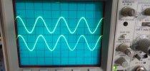
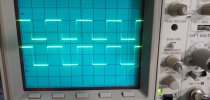
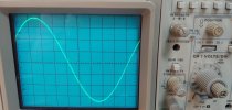
I do have a scope. I ran a 1k signal through the amp when doing adjustments and checking clipping. Wave forms looked fine. But I did not observe for very long.

What am I looking for and what should I feed the inputs?
 
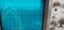
Here are some photos of the output with output level just under 1/2 watt, with 20kHz sine wave input, 2kHz sine and 2kHz square wave. Outputs into 8 ohm non-inductive resistor dummy loads for first three photos. Last photo is 2kHz sine wave into speakers.

The amp was not running for very long when these photos were taken. It was warm, certainly not hot.
 

Attachments

  • 20kHz SineWav1.jpg
    20kHz SineWav1.jpg
    69.6 KB · Views: 3
  • 2kHz SineWav1.jpg
    2kHz SineWav1.jpg
    75.4 KB · Views: 3
  • 2kHz SquareWav1.jpg
    2kHz SquareWav1.jpg
    69 KB · Views: 3
  • 20kHz SineWav2.jpg
    20kHz SineWav2.jpg
    68.1 KB · Views: 2
  • 2kHz Speakers1b.jpg
    2kHz Speakers1b.jpg
    65.2 KB · Views: 1
Last edited:
Back
Top Bottom