• The move to the new server is done. There are some software and database maintenance updates in process. This has us passing the hat around to help out. We appreciate any donations. Seriously, even a dollar helps. The payment page may be found here - https://www.audiokarma.org/support.html

SAE 2400L Restoration

Would turning the bias down to 1.1VDC across that 62ohm resistor VS the 1.27VDC have any appreciable effect?
 
Ham - your suggestion to lower bias did the trick.

I dropped bias to 1.1v and the amp runs cool as cucumber. Output heat sinks ran about 80-82 degrees, which is cool to the touch. The drive boards get pretty warm, about 110 on the heat sinks and the big resistors in the bottom corners of the drive boards get up to about 140, but I have them mounted about 1/4" above the board and they are 3 watt rated.

I ran the amp for about 3 hours last night to dial in the adjustments, and running again today for about 3 hours so far, and it does not get hot at all. Heat sinks under 90F while running music at 1.5w steady.

I checked for distortion today and got the best distortion readings of about 0.07% THD at 1kHz @1W with bias tweaked to about 1.14v which is where I left it. So slightly above 1.1, but not much and still running cool.

One more odd thing, as if there have not been enough with this unit. When powering down, the relays cut out immediately as they should with the modification. There is no squeal from the caps discharging, except when I disconnect the input, then it squeals until the caps discharge. I am testing with a phone as the source, so I have unplugged it a few times right after power down. When in a more permanent set-up, it is unlikely I would disconnect the inputs so soon, so there is no problem. But thought it was strange since the relays are already disengaged when it starts.

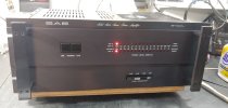
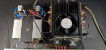
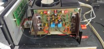
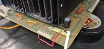
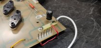
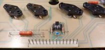
Here are some photos of the completed unit.
 

Attachments

  • 0621231759_HDR.jpg
    0621231759_HDR.jpg
    61 KB · Views: 30
  • 0621231735a_HDR.jpg
    0621231735a_HDR.jpg
    70.5 KB · Views: 29
  • 0621231735b_HDR.jpg
    0621231735b_HDR.jpg
    77.5 KB · Views: 29
  • 0621231735_HDR.jpg
    0621231735_HDR.jpg
    97.4 KB · Views: 29
  • 0620231953.jpg
    0620231953.jpg
    73.4 KB · Views: 28
  • 0620231658_HDR.jpg
    0620231658_HDR.jpg
    65.5 KB · Views: 28
  • 0620231656.jpg
    0620231656.jpg
    73.2 KB · Views: 30
You'll notice the same thing on the bench without a load. You will get an output without the relays energized because of the capacitor across the relay contacts, C39 and C40.
 
The next time I get a 2400 on the bench I'll do the THD alignments and then get some voltages for you guys without analyzers. Probably the best place to measure would be the .125 Ohm emitter resistors but they are bitch to get to. I'll also get the voltages you've been trying use. I've had a dead 2400L on the shelf for few years now so maybe it's time to get it up and running. I've got plenty of output transistors now, this week I picked up 100 each of 21195/6 since they're the only thing available now and for the near future.

Craig
 
Last edited:
OK here are the results of voltage measurements AFTER adjusting for .04% THD at 1W @ 20KHz. Voltage across BOTH .125 Ohm resistors (.25 Ohms total) is a whopping 4mv for 16ma. Voltage collector to collector of the VAS transistors is 2.27VDC. QC is 1.7VDC. Transistors used for this repair are MJE15032/33 for the VAS, MJE15028/29 for the drivers, and MJ21193/4 for outputs.

This is a lot less than it's cousin Ampzilla which is nearly 77ma.

I rebuilt this 2400L a few years ago and it came back last week with no left channel. Found no + swing of the output. Swapped driver boards, no change. Pulled both 94s on that channel to find them measuring funny and arc marks on the emitter pin of one of them. The arc marks can only be one thing loose transistor sockets, replaced all eight of them and we're back in business. I think I'll start replacing all sockets from now on.
 
Last edited:
Back
Top Bottom