

You are using an out of date browser. It may not display this or other websites correctly.
You should upgrade or use an alternative browser.
You should upgrade or use an alternative browser.
SAE 2401 Rebuild
- Thread starter hamrules
- Start date
Register to hide this ad


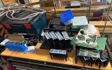
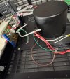
Have some bolts in it just to hold together for now.
Put a new switch in as the one in it had seen better days.
The upper right corner is bent, will work on that later.
Unfortunately the handles are MIA so not sure there. Finding some would be a miracle so either use a bolt with some head that looks good or I could install handles from a 2400(L) with minimal effort. Not sure. Oops, they use two different length spacers.
Anyone have a couple extra spacers they don’t know what to do with.
Last edited:


RVT1K
Super Member
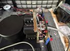
I want to replace the main caps but I’m not sure my soldering iron is good enough. We will see.
I have enough MJ21195/96’s to replace the Toshibas so we’ll go that route.
Did I say I hate thermal paste, argh.
I have, on many an occasion, resorted to using two irons when one didn't have enough punch.

I was halfway designing a new main cap PCB to fit a bunch of smaller ones. The wide flat ones sure are strange.
Good luck!
Good luck!

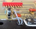
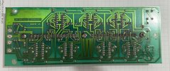
Bottom side of output board. This is where the bias adjustment pot is located. You can see where there is a piece of, what looks like wire, connecting two terminals. The actual circuit board has no connection there but the board layout drawings for the 2401 show there is a connection.
Last edited:
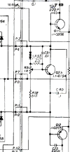
Here’s a shot of the circuit from the schematic. It shows a resistor (120 ohm) that should connect those points and not just a “wire”.
I’ve checked schematics and even the P500/A1001 shows the 120ohm resistor. Unfortunately what I don’t have yet is an actual pic of an A501 to see if that resistor is on the board.
Last edited:
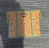

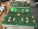
Got the caps off. Trace side a little dinged but not bad. Probably hit it with conformal coating, only cause I have a spray can here.
Did I say they were glued on also, yes I did, what a pain.
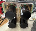
And for the testing news. Two caps tested great, one a little high on ESR and the last one was was high UF wise and high ESR. All in all not bad but I think these amps could fair better with them replaced. Problem being it’s a total pain, probably need a new circuit board for something readily available.
Waiting on new parts now, hopefully by weekend.
Last edited:
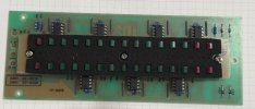
While you are in there....lol....Do you see a way to add a pot to dim the leds on the power meters and maintain full function?View attachment 3785818
CR38 is incorrect on board, should be opposite like CR31.
TIA
When I went through my 2300, I replaced all the leds when some were found bad and the replacements are WAY too bright.I do not understand why that would be something to want to do?


Similar threads


- Replies
- 16
- Views
- 3K


