

You are using an out of date browser. It may not display this or other websites correctly.
You should upgrade or use an alternative browser.
You should upgrade or use an alternative browser.
SAE 2401 Rebuild
- Thread starter hamrules
- Start date
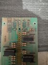
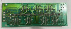
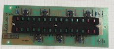
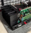
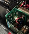

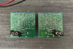
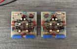
Gain cards are done. Put a 470K resistor in the select spot for a start. One had a 750K the other IDK as I lost the resistor.
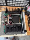
Still a little work on the one output board and then install it. Getting closer slowly.
Darn, another part MIA. Will have to wait another week now.
Last edited:

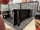

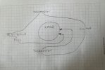
This is how I wired the AC power into the unit from the schematic and here is why I posted this.
So, this morning I go out and hook it into power directly, nothing. No noise, no smoke, no clicking nothing, just dead as a doornail. Well, what the heck as it was working last night on DBT. Re-hooked up DBT - nothing.
Checked the fuse - good.
Replaced fuse anyway - nothing.
Pulled the O/P modules off to get at the wires on the thermostats - Thermostats showed continuity as they should.
Checked the switch and it was also working as it should.
Started checking continuity from plug into the wiring. Well, something is odd here since only one side of the plug was getting continuity for both sides of the wiring. Disconnected the main wire in from the transformer wire. Well now the continuity checked out everywhere as it should. Hooked the transformer wire back to the power in and it's all messed up again.
Last edited:
Took the o/p modules out along with the front end. Once again tested switch & thermostats and all good. Tested thermostats terminals to ground & all good. Tested I/p into transformer and looks good. Wired AC direct to transformer and metered 119volts on outputs, across both outputs so that’s good. Did the same with supply for panel and that was 11volts so thats good. I’m getting really puzzled now. I think I need to re-connect the bridge rectifiers and see what’s going on there and where they go into the filter caps.
Put new bridge rectifier in. 158vdc both sides plus to minus. 79vdc both sides plus and minus. Also relays kick in after 5ish seconds.
I’ve got some new wire coming to re-wire all the thermostat/ switch stuff so there’s no spliced wires like there now.
I’ve got some new wire coming to re-wire all the thermostat/ switch stuff so there’s no spliced wires like there now.
Last edited:
Finally had a chance to re-wire all the AC lines. No spliced wires anymore. All long enough to take apart without it being hassle. I also replaced the power switch as the one I had in it just seemed like it wasn't right. Anyway it powered right up and relays kicked in after 5 seconds or so. I’m leaning towards the power switch being the actual issue. But now it’s time for some DMM checking & adjusting.
Fired it up and did some checking.
DC Offset around 28mv both sides, little higher than I wanted but it's livable.
Quiescent Current around 625mv both sides, little low will need to pop in some higher resistance and see. 470K right now I have 750K and 1M that I could try.
Bias, B channel was sitting at 1.06vdc will tweak latter. A channel is at .525vdc now that's low. It does adjust but not that much.
DC Offset around 28mv both sides, little higher than I wanted but it's livable.
Quiescent Current around 625mv both sides, little low will need to pop in some higher resistance and see. 470K right now I have 750K and 1M that I could try.
Bias, B channel was sitting at 1.06vdc will tweak latter. A channel is at .525vdc now that's low. It does adjust but not that much.
Last edited:
Put in a 750K for the QC and it jumped up to about 760mv. I think I will put in the 1M and see what I get, might be just about right. We will see.
So for the BIAS I was going over what I did and on this A channel there were two transistors that I left alone. So, I pulled them and put in new ones and low and behold it fired up with 1.03vdc for BIAS. They were Sanken 1859A & 4883A, maybe they were bad or counterfeit, who knows doesn't matter.
So for the BIAS I was going over what I did and on this A channel there were two transistors that I left alone. So, I pulled them and put in new ones and low and behold it fired up with 1.03vdc for BIAS. They were Sanken 1859A & 4883A, maybe they were bad or counterfeit, who knows doesn't matter.
Bias at 1.1vdc both channels now.
QC I put the 1M resistor in both sides. It slowly climbs to 900+mv both sides. If I blow on the card (either side) it slides right down to the 875ish mv. Since I have no area in the house and do this stuff in the garage where it's ridiculously hot, once it goes into the house it should settle out just right.
QC I put the 1M resistor in both sides. It slowly climbs to 900+mv both sides. If I blow on the card (either side) it slides right down to the 875ish mv. Since I have no area in the house and do this stuff in the garage where it's ridiculously hot, once it goes into the house it should settle out just right.
Last edited:


What switch did you use to replace it, new or NOS? IIRC it was a Leviton wall switch?Forgot, I took the old switch apart. The contacts were toast in it, welded/melted. So I guess that probably was the real power issue when it was off the DBT.
Same thing, I have some used ones.What switch did you use to replace it, new or NOS? IIRC it was a Leviton wall switch?
Similar threads


- Replies
- 16
- Views
- 3K


