• The move to the new server is done. There are some software and database maintenance updates in process. This has us passing the hat around to help out. We appreciate any donations. Seriously, even a dollar helps. The payment page may be found here - https://www.audiokarma.org/support.html

Sansui 7070 no power, please help

amason2308

New Member
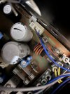
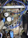
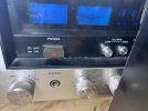
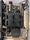
Hi, long time lurker, first time poster here. I’ve had a Sansui 7070 for about 7 years, with it hooked up to a laptop + projector as part of our family home theatre setup. Though I don’t think I have speakers that match very well (90s Polks) I’ve always loved this receiver. Unfortunately my kids had the laptop volume low and receiver volume cranked all the way up and something has blown inside. I checked the four main fuses (5V on the outside, and the 3V, 7V, and 7V on the inside) and all are fine. When I try to power on I don’t see or hear anything, not even the relay clicking. Would someone with far more knowledge than I direct me where to look next? I’m comfortable with a multimeter and changing components, but I need some help directing me on where to look. Thanks in advance, folks on forums such as this are always so passionate and helpful.
 

Attachments

  • IMG_4250.jpeg
    IMG_4250.jpeg
    169.3 KB · Views: 28
  • IMG_4253.jpeg
    IMG_4253.jpeg
    102.4 KB · Views: 29
Register to hide this ad
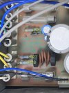
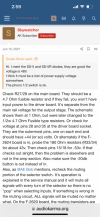
R27 = 1 ohm
R28 = 1 ohm
R29 = 4.7 ohms
 

Attachments

  • IMG_4258.jpeg
    IMG_4258.jpeg
    109.7 KB · Views: 11
  • IMG_4259.jpeg
    IMG_4259.jpeg
    135 KB · Views: 9
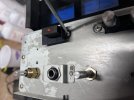
With the receiver plugged into the wall, I get power to the unswitched outlet in the back, but not to the switched outlet.
 

Attachments

  • IMG_4260.jpeg
    IMG_4260.jpeg
    132.4 KB · Views: 5
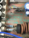
I checked the four main fuses (5V on the outside, and the 3V, 7V, and 7V on the inside) and all are fine.
AC or DC ? ( AC ) Pull the fuses and measure there resistance with your multimeter. Looks like they could use a cleaning at least.. :biggrin:
 
Hmmm, I already tested for continuity on all of them and they all produced a beep, but here are the resistances as well…

The exterior back one (5A) = 0.0-0.2 ohms
F02 (7A) = 0.0-0.2 ohms
F03 (7A) = 0.0-0.1 ohms
F04 (3A) = 0.0-0.2 ohms

I also cleaned up the 2 dirty ones with some isopropyl using a cotton swab :)
 

Attachments

  • IMG_4271.jpeg
    IMG_4271.jpeg
    134.7 KB · Views: 11
I also found an old post that suggests R27 and R28 should be reading 4.7 ohms (see attached). I got 1 ohm on both of these. Are these resistors the likely culprit?

Or is the schematic correct and 1 ohm is fine?
 

Attachments

  • IMG_4274.png
    IMG_4274.png
    198.9 KB · Views: 7
  • 1694287174263.png
    1694287174263.png
    245.4 KB · Views: 7
Last edited:
Plug something in the switched outlet and hit the power switch on the front of the receiver. Does the thing plugged into the switched outlet work? Yes, power switch ok. No, power switch bad.

Rob
 
Yes, with unit plugged in, unswitched works, switched does not. Thank you everyone, it feels good to have narrowed in on the problem!

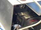
I have removed the knobs and taken the faceplates off. I have removed the front screws securing the power switch to the frame, but I still can’t remove the switch without first taking off the black plastic button at the front. Is there a good way to do this? I feel like it should pull off (similar to the knobs) but if so it is a very tight fit. I am reluctant to pull too hard for fear of breaking it. Any tips?
 

Attachments

  • IMG_4357.jpeg
    IMG_4357.jpeg
    92.8 KB · Views: 11
  • IMG_4360.jpeg
    IMG_4360.jpeg
    74.5 KB · Views: 12
  • IMG_4361.jpeg
    IMG_4361.jpeg
    72.6 KB · Views: 11
  • image.jpg
    image.jpg
    105.7 KB · Views: 11
You probably could just trace the wires coming of the power switch back to the other end, and with the unit unplugged check for continuity of the switch where the wires end with meter on ohms or the sound signal if your meter has that function.
 
Thank you DougBrewster! I will just have to be careful.

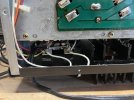
I did take the bottom baseplate off also, to trace those wires running from the power switch properly. They go to the switched/un switched sections at the back of the unit. No continuity :( So must be the switch itself.
 

Attachments

  • IMG_4365.jpeg
    IMG_4365.jpeg
    87 KB · Views: 8
  • IMG_4371.jpeg
    IMG_4371.jpeg
    116.4 KB · Views: 8
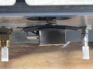
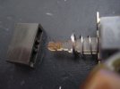
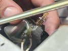
Ok, once I knew it was supposed to come off I pulled on it properly and it popped right off. Should I be buying a replacement part or trying to troubleshoot this broken switch? I’m also wondering if that other component could be a problem (a capacitor I think based on the schematic)
 

Attachments

  • IMG_4376.jpeg
    IMG_4376.jpeg
    76.5 KB · Views: 13
  • IMG_4374.jpeg
    IMG_4374.jpeg
    98.8 KB · Views: 13
Back
Top Bottom