


You are using an out of date browser. It may not display this or other websites correctly.
You should upgrade or use an alternative browser.
You should upgrade or use an alternative browser.
Sansui 7070 no power, please help
- Thread starter amason2308
- Start date
-
- Tags
- sansui sansui 7070
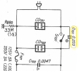

Nope.. Refers to the capacitance of that snubber cap C701 across the switch.. .033µf.. (microfarad = µf)I'm assuming the 0.033 units is V,
amason2308
New Member
Ok, thank you for clarifying that.
Good news! I decided to play with the switch while connecting my leads to those unswitched/switched leads again. It didn’t show continuity the first few times, but I found if I fully depressed the switch I would get a beep. Kept clicking the switch a few more times and now the switch seems to be working correctly, getting a solid beep when the switch is in the on position (not fully depressed by my finger this time). Does this mean it’s working now?!?
I decided to plug it in to see if this was real, and I hear the relay come on after a few seconds. Plugged something into the switched outlet - that works too
So the switch now seems to be working again. My question is - is it a good idea to spray deoxit in there and keep flicking the switch a few more times to clean any contacts in there? Or should I just leave the switch alone now?
Good news! I decided to play with the switch while connecting my leads to those unswitched/switched leads again. It didn’t show continuity the first few times, but I found if I fully depressed the switch I would get a beep. Kept clicking the switch a few more times and now the switch seems to be working correctly, getting a solid beep when the switch is in the on position (not fully depressed by my finger this time). Does this mean it’s working now?!?
I decided to plug it in to see if this was real, and I hear the relay come on after a few seconds. Plugged something into the switched outlet - that works too
So the switch now seems to be working again. My question is - is it a good idea to spray deoxit in there and keep flicking the switch a few more times to clean any contacts in there? Or should I just leave the switch alone now?
amason2308
New Member
FYI the receiver still doesn’t seem to be working, even though that switch seems to be working and the relay clicks on. I get no lights on the front and no sound from headphones or speakers. Assuming the switch is fine now, where should I look next?

amason2308
New Member
Hmmm, I thought if the relay was coming on then the power switch must be working properly now. So it could still be the power switch even though the relay is coming on?
amason2308
New Member
Hi all,
I'm hoping someone can help me troubleshoot this a bit further. I don't want to hassle anyone, it's just that I'm new to this and I don't want to damage anything. My apologies if any of my questions seem dumb. It's all still pretty new to me.
The power switch doesn't seem to be the problem (at least not anymore).
- I get continuity across the power switch when turned on, no continuity when turned off.
- I get power at the switched outlet when power switch turned on with receiver plugged into the wall.
- I hear and see the relay click on (1 click) about 5 seconds after turning on the power switch with receiver plugged into the wall.
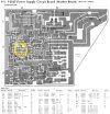
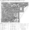
It looks like the next thing after the switched outlet is (a) the big power supply and then (b) the power supply board (F-2625). The F-2625 is where the relay is (see pic attached) so presumably power is making it to parts of this board but not all of it? Other than the relay clicking on there are no signs of life coming from the receiver when I switch it on, so my best guess is that this board is where the problem is. Other than the fuses (all tested fine using continuity test) are there any other tests I can do on this board to narrow in on the problem?
Many thanks in advance,
Al
I'm hoping someone can help me troubleshoot this a bit further. I don't want to hassle anyone, it's just that I'm new to this and I don't want to damage anything. My apologies if any of my questions seem dumb. It's all still pretty new to me.
The power switch doesn't seem to be the problem (at least not anymore).
- I get continuity across the power switch when turned on, no continuity when turned off.
- I get power at the switched outlet when power switch turned on with receiver plugged into the wall.
- I hear and see the relay click on (1 click) about 5 seconds after turning on the power switch with receiver plugged into the wall.
It looks like the next thing after the switched outlet is (a) the big power supply and then (b) the power supply board (F-2625). The F-2625 is where the relay is (see pic attached) so presumably power is making it to parts of this board but not all of it? Other than the relay clicking on there are no signs of life coming from the receiver when I switch it on, so my best guess is that this board is where the problem is. Other than the fuses (all tested fine using continuity test) are there any other tests I can do on this board to narrow in on the problem?
Many thanks in advance,
Al
Attachments
amason2308
New Member
Anyone?
Alternatively, can someone recommend a tech in the NY/NJ area?
Alternatively, can someone recommend a tech in the NY/NJ area?

The fact that the relay is clicking is a good indicator you don't have major problems with the power amp section. 
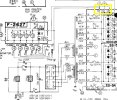
Lets do a quick check of the dial lamp power supply. It is a simple AC secondary winding. Note on the following image
at the top of the transformer symbol you have whit(e) whit(e) wires on pins 11 and 19. One side (11) goes to the ground bus
and the other goes through fuse F04 and out to power the lamps.
Set the meter to read AC volts and clip one lead to the chassis and touch the other probe to each end of the F04 fuse.
With the power on you should have something in the neighborhood of 6 to 8 volts AC.
If you have voltage on both ends of the fuse the lamps should be working. So lets see what you have and go from there.
You can see where the lamp power leaves the board on pins 72,73,74 and goes out to various places.
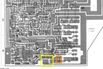
Lets do a quick check of the dial lamp power supply. It is a simple AC secondary winding. Note on the following image
at the top of the transformer symbol you have whit(e) whit(e) wires on pins 11 and 19. One side (11) goes to the ground bus
and the other goes through fuse F04 and out to power the lamps.
Set the meter to read AC volts and clip one lead to the chassis and touch the other probe to each end of the F04 fuse.
With the power on you should have something in the neighborhood of 6 to 8 volts AC.
If you have voltage on both ends of the fuse the lamps should be working. So lets see what you have and go from there.
You can see where the lamp power leaves the board on pins 72,73,74 and goes out to various places.
Last edited:
amason2308
New Member
@mrk229 thank you for the response. I really appreciate the help! I am out of town right now for work, but I am going to try this test when I return and will post back here with results.
I am also very happy about this... The fact that the relay is clicking is a good indicator you don't have major problems with the power amp section.
I am also very happy about this... The fact that the relay is clicking is a good indicator you don't have major problems with the power amp section.
amason2308
New Member
@mrk229 , good news I think
I did as you suggested with the multimeter and got the following:
Both sides of F04 = 6.8V
Pin#72 = 5.8-6.8V
Pin#73 = 0.024V
Pin#74 = 0.024V
Other observations:
- Doing the test on F04 and pin#72 makes the lamps light up and stay on (at least for a while)
- Doing the test on F04 not only makes the lamps come on and stay on, it also makes the lamps a little brighter
- Seeing the lights come on made me excited so I decided to try adding a source and plugging in headphones. I am getting very faint sound from the headphones, but I can hear the music coming through. It's just not very loud. I did this test with AUX and AM and got sound. Nothing from the FM though.
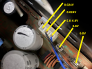
I did as you suggested with the multimeter and got the following:
Both sides of F04 = 6.8V
Pin#72 = 5.8-6.8V
Pin#73 = 0.024V
Pin#74 = 0.024V
Other observations:
- Doing the test on F04 and pin#72 makes the lamps light up and stay on (at least for a while)
- Doing the test on F04 not only makes the lamps come on and stay on, it also makes the lamps a little brighter
- Seeing the lights come on made me excited so I decided to try adding a source and plugging in headphones. I am getting very faint sound from the headphones, but I can hear the music coming through. It's just not very loud. I did this test with AUX and AM and got sound. Nothing from the FM though.
@mrk229 , good news I think
I did as you suggested with the multimeter and got the following:
Both sides of F04 = 6.8V
Pin#72 = 5.8-6.8V
Pin#73 = 0.024V
Pin#74 = 0.024V
Other observations:
- Doing the test on F04 and pin#72 makes the lamps light up and stay on (at least for a while)
- Doing the test on F04 not only makes the lamps come on and stay on, it also makes the lamps a little brighter
- Seeing the lights come on made me excited so I decided to try adding a source and plugging in headphones. I am getting very faint sound from the headphones, but I can hear the music coming through. It's just not very loud. I did this test with AUX and AM and got sound. Nothing from the FM though.
View attachment 3005873
What you have said here makes me think you have some bad solder joints on the pins at 72,73 and 74. 6.8 volts on both side of the fuse is great.The fact that the voltage varies on 74 is a clue and the big clue is the fact the lamps came on when you were probing that area.
Have a good look at the bottom of the circuit board where those pins are. Wiggle the plug a bit while you are looking at the solder joints.
I would go ahead and re-solder the pins. If that does not do it then the wires that are crimped on the contacts in the socket need looked at. We will cross that bridge if needed.
Check the solder joints first. Once the lamp issues are resolved we can move on.