• The move to the new server is done. There are some software and database maintenance updates in process. This has us passing the hat around to help out. We appreciate any donations. Seriously, even a dollar helps. The payment page may be found here - https://www.audiokarma.org/support.html

Sansui 7070 no sound

hensur

New Member
Hello,
I'm new to this forum because I'm trying to fix my dads old Sansui 7070 receiver. He also had two ESS Speakers which he gave to restoration a week ago. So I tried to get the amplifier he bought with them to work again. He told me it was laying in the basement since it stopped working, which is about 10 years ago.
The amplifier doesn't give sound, but everything else seems to work. I attached a FM antenna to it and got a signal, the FM Stereo indicator turned red.
However, I can't get any sound out of it. The headphone jack doesn't work and the speakers stay silent.
I already checked the 3 fuses on the F-2625 board, but they seem to work. I've read about the protection relay which should click a few second after turning the amplifier on, but I couldn't hear anything. I've also measured the output voltage at the speaker terminals which is about 4V.

I hope you can help me here.

Thank you,
Henning
 
Register to hide this ad
If the relay isn't clicking, you shouldn't have voltage at the speaker terminals. If you are seeing 4V there, something is seriously wrong. Don't connect speakers to it. Check the voltage at pins 37 and 50 on board F- 2625. Odds are the 180 ohm fuse resistors R33 and R34 on the driver board, F-2624 are open. This is a common issue for that board.

- Pete
 
The voltage at 37 and 50 is about 0.03V.
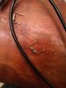
The two resistors (R33,R34) seem to be faulty. I tried to measure their ohms, but my multimeter showed them out of range. So I tried to check them in diode mode, but I couldn't get a connection through them. They doesn't look good, either, I attached a picture.
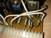
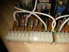
I didn't measure the other resistors on the board, but, as you can see in the pictures, they look damaged as well. Would it be useful to replace them as well while I'm on it, so I don't have to do this again next year?
Are these fuse resistors a special type of resistors or can I use normal ones? If they are, where can I get them?

Thanks for your help
Henning
 

Attachments

  • IMG_20151026_221854.jpg
    IMG_20151026_221854.jpg
    43.4 KB · Views: 118
  • IMG_20151028_084327.jpg
    IMG_20151028_084327.jpg
    81.9 KB · Views: 123
  • IMG_20151028_084359.jpg
    IMG_20151028_084359.jpg
    79.3 KB · Views: 116
Out of range means open circuit. Those resistors are bad and need to be replaced. In your pictures, all those grey/blue resistors are fuse resistors and many will have higher resistance than they should and should be replaced as well. There are 150 ohm, 10 ohm and 4.7 ohm fuse resistors on that board in addition to the two 180 ohm resistors you have already removed. If you are going to place an order to buy resistors, get them all. This is a well known issue for that driver board.

- Pete
 
I did just order a set of resistors with different values. All the values you mentioned are in it. According to the Service Manual all of them should have 1/2W, except the 180ohm ones, but I could only find a 1/4W set, is it important to have 1/2W instead of 1/4W ? I also found some bad resistors on the F-2625 Power Supply board R27,28,29 (4,7Ohm). I guess it would be good to replace them as well.
 

Attachments

  • sansui7070_power.png
    sansui7070_power.png
    507.7 KB · Views: 47
It would be better to have the right wattage but going down rather than up is probably OK but they will be more prone to failure. You will need multiples of many of the resistor values to replace them all on that board. How many of each value are in the kit? Not all the fuse resistors on that board commonly fail so if you don't have enough of a particular value, just replace the bad ones. Replace the bad ones on the power supply board too.

- Pete
 
I have 20 of each value. I think that should be enough for the two boards.
 
Last edited:
I replaced the resistors and the relay clicks now. But still no sound from the speakers. The voltage at the speakers output is now at 0V. Also, the lights at the front panel won't show up anymore. I tried to use the AUX Input, but I see no change from the wattage meter when I increase the voltage and I hear no sound.
 
The voltage at the speaker terminals typically won't be zero unless you adjusted it to zero. Even then it will dance around a little. Is the speaker switch turned off? Is it in A+B with only one set of speakers connected? Are the tape monitors set correctly?

- Pete
 
I didn't adjust it, I selected the A Speaker output, which is also where I connected the speakers. I measured the voltage again on my multimeter's smallest step. The voltage was really low, nearly 0, but I could see small changes from 0 to 0.002 V. Maybe this is because there is no input signal generated since the front panel doesn't work?
 
I replaced the resistors and the relay clicks now. But still no sound from the speakers. The voltage at the speakers output is now at 0V. Also, the lights at the front panel won't show up anymore. I tried to use the AUX Input, but I see no change from the wattage meter when I increase the voltage and I hear no sound.

This is probably as expected, when an input other than FM or AM is selected, the lights are often turned off.

I didn't adjust it, I selected the A Speaker output, which is also where I connected the speakers. I measured the voltage again on my multimeter's smallest step. The voltage was really low, nearly 0, but I could see small changes from 0 to 0.002 V. Maybe this is because there is no input signal generated since the front panel doesn't work?

I am not convinced the speaker relay is closing, how about marking the present position of both the DC offset trimmers, (with a sharpie?) set yourself up to measure DC offset at the speaker terminals (as above) - and very gently adjust the DC offset trimmer for the channel you are monitoring with your meter. If you CAN see a voltage change when adjusting - then it looks like the relay is closing. Reset the DC offset to as close to zero volts as possible.

If the relay IS closing (as tested above)...

Regarding no sound coming out, what are you using as an input source?.. and are you absolutely sure you do not have one of the front panel switches in the wrong position, thus preventing audio from getting to the speakers?
 
Last edited:
I don't think there is a signal at the speaker terminals. There would be some voltage there regardless of front panel switch position. I wouldn't jump into tweaking trimmers until you figure out what's going on there. It could be because the relay isn't closing, or the relay contacts are messed up, or there are bad contacts in the speaker selector switch. Also, I don't know off hand if the 7070 puts pair of speakers in series like the DB receivers. If so, the speaker switch must be in A only or B only. If it's in A+B or A+C, the signal won't come through the speaker switch unless there are two pairs of speakers connected.


As far as the front panel lights, they should be on all the time on a 7070. If they are not on, check fuses and bulbs before anything else.

- Pete
 
I checked the voltage while trimming the DC offset, but nothing changed. It stayed the same all the time. Although I heard the relay clicking and could also see something moving in it. The speaker switch was always set to A, is there anything else which could prevent the audio to get to the speakers?

I tested the FM input, I had an antenna attached and could also get a signal when the front panel was still working. I also checked it with the AUX input and attached my phone on the highest volume to it.

The front panel lights did work randomly before I replaced the resistors. Sometimes I had to power it on and off for about 3 times to get them working. I checked the three fuses on the power board F-2625, they seem to be fine. Are there other fuses I should check?
 
your problem seems to be between the output transistors and the speaker terminals ... it could however be before that in the circuit ..
if there is a main in did you try plugging something into it yet ? or if jumpers just touch them with a finger and see if it hums from speakers
 
Somehow the lights are working again. I didn't do anything except waiting. I plugged in my phone on the AUX port again and could the some voltage changes on the B Speaker output but not on the A one. So the relay definetly works.
Also I can't get the FM tuner to get a signal on the same frequency I got one before.
 
I am thinking you have lost the B+ main supply to the output transistors - possibly blown fuses.
 
If you are driving the aux in with your phone's headphone jack and turned the phone's volume up to max, you may have overdriven the input and blown something on the EQ board. That's not the problem in the output though. You need to check the DC Offset at a point before the speaker relay. On the power supply board there are two copper coils, L01 and L02. Each has a 4.7 ohm resistor in parallel with it. Check the voltage at the junction between the coil and the resistor. You should be able to adjust the DC Offset at those points.

- Pete
 
Something isn't right. Is your meter set to DC volts? If it's not auto-ranging, is the range set correctly? Is the driver board installed? How many resistors did you change? Are the right values in the right locations? Are all the new solder joints good?

- Pete
 
I have the same problem with a sansui 7070. I had it sitting in my garage and it was working awhile ago. Someone gave it to me. Now, I also get 4 volts on the output, the relay doesn't click, but all controls lights work, but no sound from either headphones or speakers. If you turn it all the way u you can hear faint audio. i haen't checked the resistors yet, but did clean all controls figuring that was the issue since it was sitting around, but didn't help.
 
Back
Top Bottom