Have a 7070 that powers on, with lamps functional, but speaker safety relay will not engage. Have gone through, some of the earlier threads on this and there is much good information, that has helped. First off, the output transistors were tested and are good. Noticed that removing the F-2624 board and powering on will engage the relay. Presently I have replaced most of the fusible resistors on the F-2624 driver board, E-caps, with the dreaded VD1212s to follow. If the relay still does not engage, then one or more transistors on the driver could be at fault. Before I go down that road, I have another 7070, that is fully functional. Would I be pressing my luck, swapping out the driver boards and risk something else upstream, potentially damaging the 2nd driver board? If so, say there is a short on the power supply board, why would the relay engage with the driver board removed?


You are using an out of date browser. It may not display this or other websites correctly.
You should upgrade or use an alternative browser.
You should upgrade or use an alternative browser.
Sansui 7070 Safety Relay Not Turning On
- Thread starter Thorbr
- Start date
Register to hide this ad

The odds are pretty good that that the relay is engaging with the board removed because the offset voltage is at or near zero.Have a 7070 that powers on, with lamps functional, but speaker safety relay will not engage. Have gone through, some of the earlier threads on this and there is much good information, that has helped. First off, the output transistors were tested and are good. Noticed that removing the F-2624 board and powering on will engage the relay. Presently I have replaced most of the fusible resistors on the F-2624 driver board, E-caps, with the dreaded VD1212s to follow. If the relay still does not engage, then one or more transistors on the driver could be at fault. Before I go down that road, I have another 7070, that is fully functional. Would I be pressing my luck, swapping out the driver boards and risk something else upstream, potentially damaging the 2nd driver board? If so, say there is a short on the power supply board, why would the relay engage with the driver board removed?
Are all fuses on the PS board good? Are the power supply voltages for the driver board all present and correct?
You did not mention if or when you checked the bias and offset voltages while replacing parts.
I would confirm you have bias and check the offset voltages and see where they are at.
Personally at this point I would not swap the driver boards and risk causing damage to a known good board. Do some more detective work on the non-working unit.
mrk229, Advice taken. Better and with less risk, to compare connector pin voltages, between the two 7070s.
In regards to bias and offset, I did not measure, as I don't think I am at that stage. Similar to what others have
reported, in earlier threads, I am getting a bit over 4VDC at the speaker outputs, with power on and driver card
installed. Which leads me to think, that it is a power supply related problem, as I can't see both output channels
failing, with identical results.
In regards to bias and offset, I did not measure, as I don't think I am at that stage. Similar to what others have
reported, in earlier threads, I am getting a bit over 4VDC at the speaker outputs, with power on and driver card
installed. Which leads me to think, that it is a power supply related problem, as I can't see both output channels
failing, with identical results.
When you say 4VDC at the speaker outputs is that literally a the speaker connections? You had said the relay does not engage, that should leave you with zero volts a the speaker connectors.mrk229, Advice taken. Better and with less risk, to compare connector pin voltages, between the two 7070s.
In regards to bias and offset, I did not measure, as I don't think I am at that stage. Similar to what others have
reported, in earlier threads, I am getting a bit over 4VDC at the speaker outputs, with power on and driver card
installed. Which leads me to think, that it is a power supply related problem, as I can't see both output channels
failing, with identical results.
There are two power supply voltages that feed the front end of the driver board. That would be a good place to start checking. You can follow them back to the PS board.
The 44 volt regulated supply (pin 5) is referenced from the F-2626 regulated 41 volt supply.

Checked again to ensure my eyes are not playing tricks. With power on and all boards installed, relay does not engage and I get 4.07 VDC, at both speaker termination points. With driver board removed, relay engages and I get 0 VDC. Will check voltages per recommendations. Thanks
I was just going over the schematic. There is some unusual stuff going on in that protection circuit, that I don't recall seeing in any other Sansui.
Do you have a couple of 10-20ohm resistors? If so place them across the speaker terminals and check the voltage again.
Also have you checked the fuse resistors on driver board? Sansui fuse resistors are noted for causing lots of problems, they usually drift high.
The most likely suspects are the 180 ohm resistors R33 and R34. Next likely are the 150 ohm resistors R41,42,43,44.
You can replace them with metal film resistors. Best bet on any of these old fuse resistors is to replace them even if they are in spec.
Do you have a couple of 10-20ohm resistors? If so place them across the speaker terminals and check the voltage again.
Also have you checked the fuse resistors on driver board? Sansui fuse resistors are noted for causing lots of problems, they usually drift high.
The most likely suspects are the 180 ohm resistors R33 and R34. Next likely are the 150 ohm resistors R41,42,43,44.
You can replace them with metal film resistors. Best bet on any of these old fuse resistors is to replace them even if they are in spec.
With the protection circuit, when I went through some of the earlier threads, there was mention, of an identical symptom, with the 4 VDC at speaker terminals. Would need to view the thread again, but as I recall one of the responses was unconcerned, which I found odd. Will check my resistor stock, but I should have at least one type.
The driver board fuse resistors were one of the first items checked and replaced, as these were mentioned extensively in the earlier threads and I have run into these on previous projects. There were several bad ones and others were out of spec Thanks again for the feedback
The driver board fuse resistors were one of the first items checked and replaced, as these were mentioned extensively in the earlier threads and I have run into these on previous projects. There were several bad ones and others were out of spec Thanks again for the feedback

Of the same wattage! With a flameproof coating! Don't go larger in the wattage !! Carbon or metal film are fine.You can replace them with metal film resistors
Well I could not resist. I popped in the driver board from my functional 7070. Lo and behold the protection relay engaged. Putting the driver board from the non-functional 7070 into the good one resulted in that protection relay not turning on. Points to a faulty driver board. More fun to follow, but at least I know where to concentrate. For the driver board, I've gone through all the resistors, caps and replaced where needed. The diodes and transistors were tested in place, with a multimeter diode test, with no shorts identified. Will recheck again along with voltage points.
I go back to my earlier thought, If you have replaced parts on the driver board then I suspect the offset voltage(s) need adjusted. Since the protection circuit is not closing the relay you will have to check them on the PS board before the relay.Well I could not resist. I popped in the driver board from my functional 7070. Lo and behold the protection relay engaged. Putting the driver board from the non-functional 7070 into the good one resulted in that protection relay not turning on. Points to a faulty driver board. More fun to follow, but at least I know where to concentrate. For the driver board, I've gone through all the resistors, caps and replaced where needed. The diodes and transistors were tested in place, with a multimeter diode test, with no shorts identified. Will recheck again along with voltage points.
Probably the easiest place is at the junction of the output transistor emitter resistors. Either lead in the blue boxes is the test point and the other end of the meter to the chassis.
Junction of R17 & R19 Left. Junction of R18 & R20 Right.
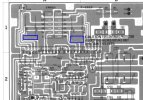
Yep 40 VDC will certainly trigger the protection circuit.Thank you. Gave it a try before I call it a night. Left channel will adjust as expected. Right is a major problem, 40 VDC with no adjustment possible. Something very wrong on the driver board, that I have yet to identify.

Go over all your work again. Look for any pads that may have lifted a bit, they can crack where they are connected to the trace. Check continuity pad to pad on a trace if unsure.
Double check resistor values for mix up. Double check transistor type and pin outs. (I'm not sure if you replaced any yet?)
I once put a transistor in incorrectly which caused a really weird issue that took me a while to find. Once I found it I pulled it out and after double checking put it right back in the wrong way again. Then visually confirmed (not) it was right (it was not) and had the exact same problem. We all make mistakes.
In the 7070, with no speaker load connected, you will find somewhere around 40v "floating", with virtually no current. There is no path to ground to drain it.mrk229, Advice taken. Better and with less risk, to compare connector pin voltages, between the two 7070s.
In regards to bias and offset, I did not measure, as I don't think I am at that stage. Similar to what others have
reported, in earlier threads, I am getting a bit over 4VDC at the speaker outputs, with power on and driver card
installed. Which leads me to think, that it is a power supply related problem, as I can't see both output channels
failing, with identical results.
You Must check the DC-Offset before the relay. If it is too high, it will never kick the relay. Use the correct trimmer to adjust it. Identify which are the BIAS trimmers and mark them so you do NOT turn them at this time.
If DC Offset will not adjust down to less then 100mV, there is a bigger problem. The relay will click at near 500mV and under, but it still needs to get close to zero. 100mV is "safe enough" to not hurt the voice coils of the speakers.
If you do not have a DBT, build or buy one before going farther. You'll thank me later.


Well I would like to think that I am not the cause of my present pain, as it was in this condition before I got it. However, I have been know to make a bad situation worse - lol.Yep 40 VDC will certainly trigger the protection circuit.
Go over all your work again. Look for any pads that may have lifted a bit, they can crack where they are connected to the trace. Check continuity pad to pad on a trace if unsure.
Double check resistor values for mix up. Double check transistor type and pin outs. (I'm not sure if you replaced any yet?)
I once put a transistor in incorrectly which caused a really weird issue that took me a while to find. Once I found it I pulled it out and after double checking put it right back in the wrong way again. Then visually confirmed (not) it was right (it was not) and had the exact same problem. We all make mistakes.
Per the owner failure mode was as follows: "I was playing an album ( vinyl). The music cut out… I heard very loud rumble/buzzing. So I turned all pieces off. Shortly after I turned on receiver, and tried to play vinyl, no sound, then tried CD, no sound." Based on that, I was sure the output transistors were fried, but they are fine. Need to ask her about the speakers, as the protection relay may not have cut out in time. Beyond that, I have not noticed any signs of obvious distress on any of the boards or components. Not even any heat traces. Will continue checking the driver board.
Thank you for the reply and advice. Attempted DC-Offset adjustment per my earlier post. Can adjust down to 0 VDC on left channel, but right is pegged at 40 VDC with no adjustment possible. All testing done with DBTIn the 7070, with no speaker load connected, you will find somewhere around 40v "floating", with virtually no current. There is no path to ground to drain it.
You Must check the DC-Offset before the relay. If it is too high, it will never kick the relay. Use the correct trimmer to adjust it. Identify which are the BIAS trimmers and mark them so you do NOT turn them at this time.
If DC Offset will not adjust down to less then 100mV, there is a bigger problem. The relay will click at near 500mV and under, but it still needs to get close to zero. 100mV is "safe enough" to not hurt the voice coils of the speakers.
If you do not have a DBT, build or buy one before going farther. You'll thank me later.
Then it seems there is definitely a problem, likely the driver board, but not definitely. Post clear photos of the F-2624 from a couple angles so we can get a looksee at it. Then we'll go from there. Running blind is not the easiest with these units.Thank you for the reply and advice. Attempted DC-Offset adjustment per my earlier post. Can adjust down to 0 VDC on left channel, but right is pegged at 40 VDC with no adjustment possible. All testing done with DBT
Be sure to have the input connector at the top of the driver board plugged in when doing any adjustments. It supplies the ground needed for the input circuit. Just an FYI so you know.Thank you for the reply and advice. Attempted DC-Offset adjustment per my earlier post. Can adjust down to 0 VDC on left channel, but right is pegged at 40 VDC with no adjustment possible. All testing done with DBT
I am convinced that I have a faulty semiconductor in the driver board Right Channel circuit. Surface testing with a DMM does not show any shorts and RH channel results compare with LH channel. Have yet to pull any components for more detailed testing, but will do so for a couple tomorrow.