• The move to the new server is done. There are some software and database maintenance updates in process. This has us passing the hat around to help out. We appreciate any donations. Seriously, even a dollar helps. The payment page may be found here - https://www.audiokarma.org/support.html

Sansui 771 restoration gone wrong, help please

Romique

New Member
Hello dear members, my name is Romulus and I am new to this forum... at least i've been reading a lot from the Sansui section and this is my first post.

Recently got a Sansui 771 in very poor shape but it was working. I've done some major restoration to cosmetics and repaired a couple of lights that were not working, i've done a complete recap of the unit, changed the relay, changed the trim pots for DC offset and bias adjustment with Bournes 25 turns.

It all worked great and the unit didn't blow up on first start after the restoration, but... I've adjusted the bias to what is specified in the service manual (19mA) with no problems, but the DC offset gave me a hard time as it was bouncing all over the place. I somehow managed to set it so it was displaying 0 mV most of the time but it was bouncing randomly between -40mV and 40mV.

The unit worked well and had good sound but i was hearing some hiss and humm from the speakers and when i was turning the unit on and the relay clicked i was hearing a slight pop from both speakers. Done some research and i've replaced all the diodes and zener diodes on the driver board and i went ahead to change the transistors as well.

So after i've changed the diodes and transistors TR01, TR02, TR03, TR04 (originally 2SA640) with some hFE matched KSA992FTA which i found on this forum to be great replacements, i gave it a go and checked the DC offset which improved a lot with small bounces of +-5mv.

After that i went ahead to changing the other transistors as i have ordered them from Digikey along with the other parts and this is where i screwed up... when fitting the new transistors which originally were 2SC1124, replacement KSC2690AYS (TR05, TR06), i accidently fitted them in the slots of the 2SA706, replacement 2SA1220A (TR11, TR12) and then i put the board back in and powered on.

After a few seconds i didn't hear the relay click but the fuse F02 had blown with a green flash. Instantly powered off the unit and checked to see what was wrong and i realized i have fitted the wrong transistors :(.
Went ahead and put in the proper transistors in the proper place, also replaced TR05, TR06, TR09, TR10 with the new KSC2690AYS substitutes, changed the fuse to a new one (the one that blew up was a 4A fuse instead of a 5A fuse like the manual states; someone was messing with this unit before) and powered on the unit. The fuse has blown again, i've triple checked if everything is well soldered in the proper place and with no solder bridges, and everything seems to be correct.

I've done some more reading on the forum and found that a power transistor can be shorted and after checking all of them i have a short between emitter and collector on TR02 (Sanken NPN 2SC1402). I figure this is what's causing fuse F02 (right channel) to pop each time i power on the unit.

Sorry for the long story, but i figure it would help any of you guys guide me into fixing this mess. I take responsibility for all the damage i have caused to the unit because of not paying enough attention. My knowledge in electronics is basic and i'm learning a lot from forum threads, Youtube and practice on this Sansui.

What would you recommend me to do next? I was thinking of ordering new power transistors and while i'm at it i would replace all four because two of them were already swapped with RCA 2N3772 before i got the unit, and one is shorted from the original ones (2SC1402).

I would appreciate some substitute suggestions that can be easily found on the international market. I'm from Romania and we don't have a wide variety of parts in our local electronics stores. There aren't too many experienced hands around locally that could check my unit and help me fix it, so i'm relying entirely on your help here on this forum.

Thanks for understanding my situation and for taking your time to help me. I can provide more information or photos of my unit as needed. I really love this stereo receiver and it had cost me a lot of money until now to get it restored and functioning properly ($300 for the unit and $200 for restoration thus far). Really love the sound it provides.
 
Last edited:
Register to hide this ad
First, make a DBT or buy one. Check all driver transistors and replace them along with output transistors. Plugged into DBT with 50W bulb and power on.
 
The 771 using all NPN transistors in the output, so hopefully you can find onsemi MJ21194 's in your market - these are excellent replacements, and best to do all 4. It is best to replace the mica insulator as well. That insulator separates the output casing ,which asc as the collector, from shorting to the heatsink (ground) - look for TO-3 mica insulators. After mounting new outputs, do a quick continuity check between casing and heasink to make sure there is no continuity.

Check your drivers too as sanjib says.and also do a thorough visual inspection on the driver boards looking for burnt resistors or other marks of heat.

Seems like you already have a transistors tester, since you matched the ingoing 992's - that is great and is one of the best tools to have next to a DBT. Even experienced guys will occationally get the pin-out wrong when swaping transistors, so here the tester, again, is invaluable.

P.S Your english is better than mine. I am from Copenhagen.
 
First, make a DBT or buy one. Check all driver transistors and replace them along with output transistors. Plugged into DBT with 50W bulb and power on.

Thanks for the sugestion, i will build a simple DBT. Is a 50W bulb enough for my 230V mains voltage?
Already changed all the driver transistors and i'm waiting for the output trannys to be delivered.

This is my fav Sansui replacement transistors goto thread. Do not buy semi-conductors from eBay or from dubious on-line websites as you will get counterfeits nearly 100% of the time. Work with a DBT!

I'm aware of ebay counterfeits and almost never purchase from ebay if i can find a more reliable source for electronic components. Luckily i can purchase prom Digikey as they have a website in Romania and they provide free shippment on orders above $50 which is nice. Only thing is, i have to pay 19% VAT... not a big deal for the very fast 3 day delivery. There are also two more online shops similar to Digikey in my country but are lacking in some component cathegories. Will use a DBT.

The 771 using all NPN transistors in the output, so hopefully you can find onsemi MJ21194 's in your market - these are excellent replacements, and best to do all 4. It is best to replace the mica insulator as well. That insulator separates the output casing ,which asc as the collector, from shorting to the heatsink (ground) - look for TO-3 mica insulators. After mounting new outputs, do a quick continuity check between casing and heasink to make sure there is no continuity.

Check your drivers too as sanjib says.and also do a thorough visual inspection on the driver boards looking for burnt resistors or other marks of heat.

Seems like you already have a transistors tester, since you matched the ingoing 992's - that is great and is one of the best tools to have next to a DBT. Even experienced guys will occationally get the pin-out wrong when swaping transistors, so here the tester, again, is invaluable.

P.S Your english is better than mine. I am from Copenhagen.

Thanks for the compliments! I use english as my second main language :)).
Already ordered four MJ21194G from a local online shop in Romania and i'm pretty sure they are 100% genuine. Also bought four mica insulators and a silicon thermal compound. Thanks for the tips on installing them correctly. I've never thought of checking for continuity between the collector and the heatsink.
I've checked each and every part on every board for burn signs and everything seems to be fine. I had no smoke coming out because the fast acting fuse blew in 2 seconds from turning the unit on.
I've checked the transistors with a cheap Yato multimeter that has a hFE test function and a transistor socket. I'm sure it's not very precise but at least i can get some informative readings and checks from it.

Thanks everyone for your replies! I will come back with more info after some parts arrive.
 
I also changed out the transistors on the Tone board and Phono Board (2SC1313) which are on the Top Ten bad transistor list with KSC1845FTA's for long term reliability and lower noise floor. Very sweet sounding unit once complete. Enjoy!
 
I also changed out the transistors on the Tone board and Phono Board (2SC1313) which are on the Top Ten bad transistor list with KSC1845FTA's for long term reliability and lower noise floor. Very sweet sounding unit once complete. Enjoy!

Now that's a nice tip to have... i was wondering if the noise floor could be lowered somehow... when listening to higher volume it is kind of loud and obvious and i was suspecting the tone board to be the culprit... After the recap job (mostly Elna Silmic II and a few Nichicon Fine Gold) my sound got a bit bright and lacking in bass... so the bass knob has to be turned to 6-8/10 and the highs to -2 so i can get a well balanced sound from my speakers.
Speakers are Kenwood KL-777 recapped with Miflex MKP-10 film capacitors which are known for brightening the highs a bit. Bass is deep and punchy but only when cranked up from the tone controls. I've noticed that it introduces some floor noise and some distortion when cranking up near maximum.
Will replace all the transistors on the tone board... If you can spare some time to give me the best replacements for all the tone board transistors i would highly appreciate and you would win me some time... my mind needs a break from searching transistors because i'm starting to dream at night about doing this for a while now. It's been two months of researching on this unit thus far and it got me a bit tired as this is the first ever stereo receiver i have worked on. I've also restored a Kenwood KA-7100 and a Yamaha R300 meanwhile with no problems.
Kenwood KR-6060 coming up next on the bench for a full recap and troubleshooting for what's causing distortion and difference in output volume on the speakers. I'm learning on the go since my knowledge in electronics was 0 when i first started out (few months ago). AK has helped me a lot in learning vintage electronics and i'm a pretty able person when it comes to restoring stuff. I learn fast and can handle any kind of equipment very well.
Thanks!
 
Hello everyone,

Finally got the output transistors along with TO-3 mica insulators, thermal compound and some transistors and diodes that i thought needed replacing.

I have also built a working DBT and got some 60w, 75w, 100w and 150w light bulbs. Tested with a working unit and bulb flashes on power on and then fades out completely. I guess i have it set up correctly.

What should i do next? Already replaced the rest of the transistors and diodes with replacements suggested in other threads by AK members and made sure to put them in correctly and in the right place. Should i put the new outputs in and give it a try on the DBT? What wattage bulb should i try to make sure nothing burns again?

I would appreciate some tips on how to properly use the DBT in this situation.

I'm patiently waiting for your replies.

Romulus
 

Attachments

  • 20210224_001706.jpg
    20210224_001706.jpg
    100.9 KB · Views: 43
After installing the components and visually checking if they are all inserted correctly (especially the output transistors) power on the unit with a 50 W bulb.

If the light become dimmer the short is gone.
Sometimes the relay will not engage as the bulb limits too much the current.
In this case you can try 60 or 75W bulb.

if the light does not dim then quickly turn off the unit.
 
Done!

Put in the new outputs and quadruple checked each transistor and each diode to make sure everything is mounted right. Crossed my fingers and hooked up the unit to the DBT and with a wildly racing heart i powered it on. The bulb lit up for under a second and went out completely. 3 seconds later the relay clicked :banana:.

Looks to me that i've done everything correctly. No smoke coming out and no obvious signs of overheating. Only one thing still buggers me... the DC offset is still bouncing all over the place :(... fluctuates around 0mV but often spykeing to -20 and +20mV.

I've replaced all the transistors on the F-1499 driver board except for TR07 and TR08 which are 2SC281. Couldn't find suitable replacements as these are the cylindrical type transistors wrapped in a metal plate and tied to TR09 and TR10 via screws to the driver board. I've replaced TR01-TR04 with hFE matched replacements (KSA992FTA). Heatsinked all the other transistors on the driver board and replaced all the diodes and zener diodes.

On the power board i've replaced TR06 (2SD330) with a heatsynked TIP31AG and diodes D05, D06, D07 and D08 with exact replacement diodes 100V 1.5A (1N5392G). Also replaced the 3 legged type diodes D01-D04 with diy diodes made out of two 1N4007 diodes each... two of them with anode common and two of them with cathode common and correctly placed on the board. New Omron relay as well.

Any suggestions on what else to check? There doesn't seem to be any browned or corroded resistor or anything on the boards, i've also throughly checked for cold solder and resoldered some joints that looked bad.

I took the DC offset measurings after 5-10 minutes of idling connected directly to the mains and with volume at 0, speakers A and AUX input selected.

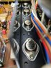
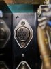
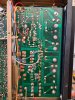
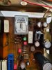
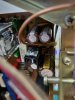
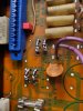
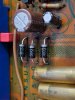
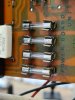
Here are some pics of the work i've done so far... maybe a more experienced eye can spot if something is out of place.

I appreciate all your help so far and would gladly appreciate more tips on what to check next. Or is it ok to use the unit like this? Didn't hook it up to speakers yet... I'm kind of scared not to cause any damage to my Kenwood KA-777's

Thanks!
 

Attachments

  • 20210228_110309.jpg
    20210228_110309.jpg
    120.4 KB · Views: 106
  • 20210228_105220.jpg
    20210228_105220.jpg
    96.2 KB · Views: 105
  • 20210228_105241.jpg
    20210228_105241.jpg
    85.6 KB · Views: 104
  • 20210228_105405.jpg
    20210228_105405.jpg
    169.8 KB · Views: 111
  • 20210228_105624.jpg
    20210228_105624.jpg
    98.6 KB · Views: 114
  • 20210228_105640.jpg
    20210228_105640.jpg
    84.6 KB · Views: 108
  • 20210228_105725.jpg
    20210228_105725.jpg
    115.3 KB · Views: 107
  • 20210228_105756.jpg
    20210228_105756.jpg
    111.1 KB · Views: 106
  • 20210228_105820.jpg
    20210228_105820.jpg
    108.6 KB · Views: 103
And forgot to mention there's humm coming out of the speakers... sounds good on both channels but at idle there's an audible humm/hiss coming from the speakers. The speaker cones aren't wobbling but they do have a vibration in them when i barely touch the cone... increasing the volume amplifies this buzz... it's kinda faint but i can hear it and it shouldn't be there. Sounds like static. Any thoughts on this?
 
are you on an unused imput?
The Volume pot needs to be at zero as well.
Yes. I am measuring while on Aux 1 with nothing connected to the amp. Volume pot is set to zero and all other knobs are set to neutral position.

does the subsonic filter or tone defeat affect the fluctuation?
When i press the low filter it spikes even higher. Pressing it multiple times seems to amplify it more. This unit doesn't have tone defeat, instead its got 20db audio muting but pressing this button doesn't seem to affect too much. Also when speakers are connected and i press either of these buttons it sends a pop to the speakers... the low filter seems to pop louder than the other buttons and pressing it multiple times sends louder pops.

Turning the unit off and then back on gives a pop as well both ways. On cold start it doesn't do the pop.

Any ideas?
 
Last edited:
So... is anyone willing to help me sort this one out?
I really want to get this restoration complete with the amp working flawlessly. It's my first and also my favorite amp so far and i want to enjoy it knowing that everything works as it should.
Maybe some of you have a clue of what might be wrong from the info i've provided in the previous replies.
I'd really appreciate your help.
Thanks!
 
Hi Moe and thanks for your reply.

Have you cleaned and deoxed the switches yet - poor contacts?

Yes i did, twice... but maybe i should go even heavier on the deox. Allthough the DC offset has the same bounce as before the cleaning was done... i'm suspecting some other faulty components honestly. The main power caps are some new and expensive Mundorf M Lytics slightly higher in voltage (63V) but same uF rating (4700uF). They are fairly fresh because they're the new model that just came out.

Also, protection relays etc. are another area where contacts can pass intermittent and wavering voltages. Sometimes a new relay from mouser etc. is the easiest way to assure clean contacts... This is something to think about.

Already swapped in a new relay from Omron... exact replacement.

Really nice posters :rockon:

Still waithing for some instructions on what to check.

Thanks!
 
Hi Moe and thanks for your reply.


Yes i did, twice... but maybe i should go even heavier on the deox. Allthough the DC offset has the same bounce as before the cleaning was done... i'm suspecting some other faulty components honestly. The main power caps are some new and expensive Mundorf M Lytics slightly higher in voltage (63V) but same uF rating (4700uF). They are fairly fresh because they're the new model that just came out.


Already swapped in a new relay from Omron... exact replacement.

Really nice posters :rockon:

Still waithing for some instructions on what to check.

Thanks!
Hi, a very humble suggestion, you have 33.0 V in the Emitter of TR05? This voltage goes to the Tone Board, maybe a low voltage here causes the bouncing of the DC offset (happened to me on a 6060 don't know exactly why). Try to compare the voltages on your receiver vs the service manual to find something off.

Good luck!
 
Thanks for your reply. Will try and do some more measurements. Just finished working on a Kenwood KR-6060 today... it had some issues with volume difference between channels and the dc offset was over 60mV on left channel. Did a full recap and changed a few diodes and adjusted bias. Dc offset turned out to be -1mV on the left channel and -2mV on the right. When i hit the tone switch it jumps to -60mV. Weird stuff and i have no ideea how to track this fault. Will do more reading. Thanks
 
Back
Top Bottom