• The move to the new server is done. There are some software and database maintenance updates in process. This has us passing the hat around to help out. We appreciate any donations. Seriously, even a dollar helps. The payment page may be found here - https://www.audiokarma.org/support.html

Sansui 8080 Service Mod - Need Guidance

yes this was in real bad shape when i got it i had to replaced the transistors resistors and capacitors on the protection board to get it running. when i pull the driver board out the meter doesn't move, that is why changed most of the components on the driver board.
i will try and deoxit the switches, one more unusual thing the relay says 28 volts dc
 
when i pull the driver board out the meter doesn't move
The VU meters? They're power meters. Without the driver amp board, there is no power consumed. How can they move?

On second thought, the protection LED turning green instantly is not a good sign. It means there's not enough time for DC levels to stabilize and it should not be that way, unless you turn the unit on/off very rapidly, in which case you would also see spikes on the VU meters. Normally, the protection boards takes a few good seconds to turn the LED green.

The relay should be a 24V. An Omron replacement relay PN is MY4-02-DC24. Some common culprits on the F-2547 protection board, other than a dirty and carbonized relay, are the old 1N60 germanium diodes (prolly can sub with 1N3595TR, look it up...), the larger values electrolytic capacitors (C1,C2 and C3) and the high value resistors. Make sure the caps are oriented correctly.
 
my receiver goes form red to green instantly is that ok?
No. There should be about a 5 - 8 second delay before the LED goes green, and the speaker relay clicks in. That is time enough for most voltages to settle down. That is also probably why the power meters "bump" at turn-on.
 
me again with a question is the thermal swithc connected to piont #19 on the protection board suppose to be open or closed?
i did find new in60s for $5 each and changed them.
 
Thank you John.
this is getting exciting... looks like the person before me made a big mess i am looking at the circuit and some of the resistors are incorrect. i am sure i will need some help soon once i get the correct components in it.
 
thank you all. i followed the voltage and landed up changing the c945 to transistors the check out ok but were not regulating the voltage once i replaced the it all started to work fine.
i am now enjoying amp.
 
Nice detective work! It sometimes is hard to stick to it, after you’ve unsuccessfully tried several fixes. :music:
 
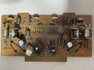
I am working on an 8080 restoration and trying to follow the SSI-0004E service manual guide and I can't figure out how to identify the points on the board they reference (eg. Connect fuse from point M to Point N or Point O depending on R44 position)? I have an F-2436-1 board. I see from the pics in this post that the right side fuse appears to go from left point on R56 to top point on R44, and R44 resistor is shifted over to go in other point on R on R56? I just dont understand why the service guide lists points unless there is a map somewhere identifying the points? I didnt see one in the service manual.
 
^ No map. It's 1976, no desktop computers, no online document sharing, big organizational mess in the technical writers division with English not being their native language, and just maybe... too much saki got involved in the way. One guy had in mind to label the contact points in the SSI, another guy thought hand pointers are just fine, and the print guys just did what they thought was right at the time. Yes, it's a contemporary Sansui plague. No news there.

If that's what keeping you from completing the SSI guide, there's an abundance of F2436-1 before/after shots on the www, so no problem there. Here's an example:

9090%20driver%20after.jpg
 
I’m resurrecting this thread. I have to do all of these service bulletins. I’ve documented what I plan to do in another thread, but I’ll rewrite it up tomorrow and present it for review. I’m not doing anything to this unit until the service bulletins are implemented. it’s a virgin 8080, working as far as I know.
 
I reviewed the service bulletin for the F-2436-1 , F-2546, F-2547 Boards. I believe the following are the only changes required. Has anyone else made these mods that can confirm? I realize there are other threads on this topic, but the pictures are poorly noted. Hopefully, this thread clears that all up.

Of Note: The top of F-2547 is not included, and it will be assumed that the changes for F-2547 below will be made as required

a. "Resistors R13+R14 should be replaced by fusing resistors of 4.7 Ohms 1/2W"
b. The Jumper connecting some relay contacts to earth has to be removed.

If anyone has those pictures, though, please do share, especially the jumper connecting some relay contacts to earth rgound.
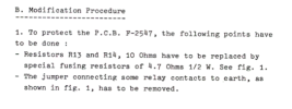
Screen Shot 2024-06-27 at 8.52.04 PM.png
F-2546
1.) Run Ground from Pin 3 to adjacent Screw
2.) Fuse Mods
a. remove jumpers and add fuse holders to F03/F04. Install 7A Fuses
b. Replace F07-F10 with 10A
c. Do I touch F02? Apparently not.
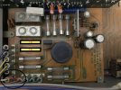
Screen Shot 2024-06-27 at 8.53.21 PM.png

IMG_0661.jpg

....Continued F-2546
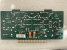
1.)Rear of the board. Remove Jumpers between points (which is really just a solder joint)
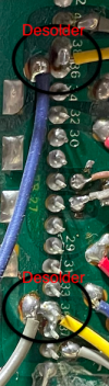
Screen Shot 2024-06-27 at 8.41.06 PM.png

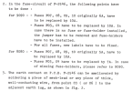
F-2436-1

a. "Check for two points of coils L01, 02 are connected to Jumper, remove the jumper" --- No jumper present that I can see. Ignore step
b. Add fuse as seen below, and remove/reposition existing resistors.
c. Add labels
d. nothing to change on the rear of the board, apparently
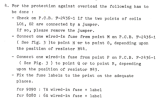
Screen Shot 2024-06-27 at 8.54.56 PM.png
IMG_0659.jpg
IMG_0658.jpg

F-2547 to F-2546 Modification were not documented. If anyone has pictures of this work please do share.
Screen Shot 2024-06-27 at 9.01.05 PM.png
 
^ No map. It's 1976, no desktop computers, no online document sharing, big organizational mess in the technical writers division with English not being their native language, and just maybe... too much saki got involved in the way. One guy had in mind to label the contact points in the SSI, another guy thought hand pointers are just fine, and the print guys just did what they thought was right at the time. Yes, it's a contemporary Sansui plague. No news there.

If that's what keeping you from completing the SSI guide, there's an abundance of F2436-1 before/after shots on the www, so no problem there. Here's an example:

9090%20driver%20after.jpg
This picture directly contradicts the service bulletin and other photos. This picture shows a fuse on R55/R56 without repositioning the adjacent resistor. As someone who is encountering the same confusion, I can see where the individual who replied last year is confused. That said, someone is selling a reproduction F-2436 board on fleabay with the same configuration shown in this picture. Nevertheless, I will follow the documentation as this board has many different configurations depending on the iteration. To screw up a Driver Board or PS Board can trickle down and royally screw everything else up. Additionally, a simple recap with existing component testing could alleviate the need for these alterations in the service bulletin. The issue was related to drifting resistors when using the receiver at top-end power usage for extended periods. I do appreciate the picture, though, because it is helpful. I believe the first step is to desolder the trouble resistors and testing them out of circuit etc.
 
I'm doing a "check-up" on an 8080 for a buddy that just acquired it. It's working after some pots cleaning but it needs all the mods. I decided to just restore the driver board while doing all the mods but I've a couple questions.
This unit doesn't appear to have fuse resistors in it. It's a Sept./75 unit (has .1uF ceramics where the 4.7uF caps should be near emitter resistors). All the resistors on the board look the same, as opposed to those easily ID'ed fusibles in the G units, & none of them are even near out of spec. Did some of these NOT have FR's or do they just not look different on these?

The subs for TR05/6 & 9/10.... This unit had the 2sc1124/2sa708 combo. This looks like the VAS portion, yes? But that combo looks to be an odd choice if so. I wasn't going to change them but one had hfe=50-ish while the other 3 were 100-120. Has anyone found the KSC3503/KSA1381 pair to NOT work well in this spot? I've seen the TTC/TTA & 2690/1220 mentioned as other options. It seems like any of the three combo's will suffice, but just curious of opinions.

I'm also curious as to why they paralleled a 4.7 ohm resistor on the back of the board across R47/48 (also 4.7 ohm) to create a 2.3 ohm path.
 
Back
Top Bottom