• The move to the new server is done. There are some software and database maintenance updates in process. This has us passing the hat around to help out. We appreciate any donations. Seriously, even a dollar helps. The payment page may be found here - https://www.audiokarma.org/support.html

Sansui AI-317 mk1 - Troubleshooting and Repair

troutmaskrep

New Member
I purchased a Sansui AU-317 off of ebay a few months ago in non-working condition to force myself to learn how to fix it. I have no background in electronics or electricity, although I did just recently complete the building of a Dynaco ST-70 and learned basic safety as part of that process.

Quick background:
- amp powers on with no relay click (i'm not focused on this aspect at the moment)
- i measured the power amp section voltages and they appear to be roughly as expected
- power section appears to be ok
- the preamp board however is not ok. the voltages are all over the place
- there are other spicy details of things I found that were not right - i will share once we get past the current hurdle

As per the attached screenshot, there seems to be a big problem at the junction of TR04 and TR06, where the expected voltage is 0.5vdc and the actual is 19vdc.
At first I thought the 8 volt drop across R16 was an issue, but ChatGPT assures me this is normal for a 1.5k ohm resistor according to Ohm's Law. I don't know if I can trust it but it did the math and it seemed reasonable.

It may be worth noting I am seeing this same 19vdc voltage in two other unexpected places - the junction of R18 and TR08 and the test point at R10.

I haven't tested any individual components yet - I don't want to get into shotgun repairs either. I may replace 'fusistors', caps etc once the fault has been diagnosed and repaired, or I may just stop there.

I'm hoping someone can interpret the schematic to point to the actual cause of the problem, or suggest a reasonable next diagnostic step.

Thank you for your time

edit: the attached schematic is of the preamp right channel
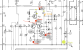
Sansui-au-317-mk1-right-preamp-section.png
 
Register to hide this ad
I should also mention, on the left channel I am seeing the same issue - where I should be measuring 0.5vdc, I am seeing 19vdc
 
Hello,
The negative rail should have been -28V. It seems to be missing a negative rail. Did you check that all the voltages at the outputs of the power supply are present and correct?
 
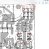
The 317 power supplies for the pre amp sections are known to suffer from dry joints on the TO220 series pass transistors TR601 and TR602 on the F-2754 main board (see screen shot below of the relevant section of the main amp board layout).


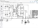
IMG_0390.jpegIMG_0392.jpegNote that the schematic has an error in regard to these +/- 28VDC supplies, see screen shot above of relevant part of the schematic.
 
Last edited:
Amazing. Thank you to all that took the time to respond. I will take more measurements and report back, but I feel like we are on the right track.
 
Be careful when reflowing, it is easy to inadvertently introduce a solder bridge/short between adjacent solder points, carefully inspect before applying power.
 
Be careful when reflowing, it is easy to inadvertently introduce a solder bridge/short between adjacent solder points, carefully inspect before applying power.
I saw that when I got in there - those pins are tiny! I inspected with a magnifying glass before applying power and luckily I didn't short anything.

TR601 & TR603 appear to be ok.

I start to see bad measurements on TR604.

So on TR 603 i see 28v on the outside pins and 42v on the center pin.

On TR604 I'm seeing -28V on one outside pin, 20V on the other, and -42V on the center pin.

Can I deduce from this that TR604 is bad?
 
I also see that R605 and R616 are the dreaded 'non-inflammable resistors'. I haven't tested them and don't have a firm enough grasp of the theory to know what effect these can have on a circuit when they go bad...
 
Ok, what you need to do is associate the outer pins of TR602 and TR604 with the board markings adjacent to those outer pins, they are marked “e” and ”b”, which stands for emitter and base (the centre pins on both are the collector). It may be that TR602 has an open collector to base junction. You will need to brush up on basic transistor testing, there is a post somewhere on the forum that provides basic guidance in testing transistors using the diode check function on a multimeter, I’ll see if I can find it.

In the mean time can you list the voltages on TR602 and TR604 as follows

TR602 b pin (base) xxxV, Centre pin (collector) xxxV, e pin (emitter) xxxV

TR604 b pin (base) xxxV, Centre pin (collector) xxxV, e pin (emitter) xxxV

re the fuse resistors, the lower value higher wattage fuse resistors aren‘t nearly as failure prone as the higher value lower wattage ones. In any case you can measure the value by setting the meter to read ohms and connect the meter probes across the resistor (with mains power off of course).
 
Here is one tutorial on transistor testing. You don’t need to remove a transistor to perform the diode check functional tests, but if a failure is suspected then the suspect transistor will need to be removed in order to confirm.

Get a lot of Q's on this, so I thought I'd put together a post.

First you need a decent digital meter with a diode test function. Forget about using the ohmmeter part of your meter, it is way too unreliable for this. Almost all digital meters nowadays have a diode test included, and it is 100% necessary for even the rudimentary reliable results that we are shooting for here. If you need to buy a meter, remember that you'll get what you pay for. Don't cheap out with a crappy $10 meter from Harbor Freight or something, when from eBay you can get a good used Fluke 77 for $30. You can buy a decent new meter for less than $100.

Just so you understand the basics of the diode function, the reading you get when you use the diode test is the voltage necessary to overcome the depletion layer at the P-N junction of the diode. Don't sweat the meaning of that, I just want you to understand the units of what you will be measuring.

If you grab a plane-Jane 1N4004 diode, for instance, set your meter for a diode test, and connect the positive lead to the anode and the negative lead to the cathode (the side with the band). You should read about 0.45V to 0.65V or so, depending on the amount of current that your meter feeds through the diode. Reverse the leads with positive on the cathode and the negative on the anode, and you should read an 'OL' or 'Overrange'...check the documentation on your meter to better understand how it will indicate an open circuit, but essentially there should be no conduction with the leads reversed. A shorted diode will show '0V' with the leads in either orientation.

Many meters give a short 'beep' to audibly indicate conduction, and a continuous 'beeeeeeeep' to indicate a short, or a very low depletion layer voltage. Handy.

Now that you know the basics of how a diode reads with a meter, you can test a transistor. The pic below shows simplified equivalent circuit of a NPN and a PNP transistor, as well as anode and cathode identification of a diode. Of course, you cannot 'build' a transistor like this, but it is a good visualization to help you understand how to check one.

Lets assume you have a transistor to test. Of course, this will require that you identify which lead is the base, collector, and emitter, and also determine if the transistor is an NPN or a PNP. Check the schematic, or the part number.

(hint: with Japanese transistors, all 2SAxxxx and 2SBxxxx transistors are PNP, and all 2SCxxxx and 2SDxxxx are NPN transistors. Often, the '2S' part of the transistor part number is omitted, thus a 2SA733 transistor is usually labeled 'A733', and the '2S' prefix is assumed)

Large TO-3 metal output transistors always have the outer case as the collector. Once you know that, you can figure out which of the other two pins are the base and emitter. Smaller transistors come in every configuration, EBC, BCE, ECB, so you need to either view the schematic to see which transistor leg connects to where, or find a data sheet for the transistor which will identify the leads for you. Of course, you can also figure it out for yourself.

Lets say you have found that you have a NPN transistor, and have identified the base, emitter, and collector. Set your meter for diode test, and place the positive lead on the base. Place the negative lead on the emitter. You should read a diode drop voltage of about 0.45 to 0.65V. Now place the negative lead on the collector. You again should read a diode drop of about 0.45 to 0.65V (these values are not written in stone...the 0.45 to 0.65V is the most common range however). Now place the negative lead on the base, and the positive on the emitter (called 'reverse biasing'). There should be no conduction. Now move the positive to the collector, and again, there should be no conduction. Lastly, move the negative to the emitter. Again, there should be nothing.

(note: most transistors fail with a dead-short from the emitter to the collector, especially in the later power stages of an amplifier. Knowing this can allow you to check high-power stages quickly for obvious failures)

For PNP transistors, the leads are reversed while doing the same checks as above (negative on the base to begin, positive on the emitter, and then on the collector etc. etc. to read the proper diode drops)

I must warn that when testing transistors in-circuit you are very likely to get voltage readings from collector to emitter, or when reverse-biasing the base-emitter or base-collector diode, all due to the multiple conduction paths in the circuit(s) that allow the meter current to flow around the component under test. Again, understand that most failed transistors short from collector to emitter, so if you read a voltage where you should not, that does not mean you have found a bad transistor. Yes, this complicates troubleshooting, but if this was easy, people would not be making a living fixing electronics. :scratch2: Bottom line...when in doubt, remove the transistor from the circuit and test it.

Last note...this type of test is generally worthless for finding transistors with 'leaky' junctions, as the voltage applied by a meter is very low and won't induce the failure. In a case like this, you will be reduced to measuring voltages with the circuit powered on to determine what is pulling excessive current, or just 'shotgunning' a whole section of the amp (replacing multiple components in the hopes of getting the bad one). Also, many old transistors will test just fine, but through age will have such low current gain that they can no longer do the job they were chosen for in the circuit. Relay driver transistors are especially bad about failures like this, where the transistor has spent hundreds of hours in a saturated state and gain eventually droops to the point that it can no longer close the relay. For this reason I replace relay driver transistors in amps as a matter of course, whether they are acting up or not.

Best of luck to ya!!
 
An edit to the post I made above re testing the resistors, it is always good practice to check if there is any residual DC voltage across a resistor before checking the value with a multimeter.

Also, if anything I have asked for, or suggested you do doesn’t make sense, then please ask for clarification , sometimes it can be difficult to convey instructions etc
 
@skippy124 nope that's perfect. I know exactly what to do next. Will report back. I will need to get a new multi-meter with a diode check function, so I won't have those measurements tonight however.
 
TR602 b pin 20.6V, Centre pin -42V, e pin 21V
TR604 b pin -28V, Centre pin -42V, e pin 21V

edit: resistors R616 and R615 test ok (both test 5.5 ohm and spec stays 4.7 ohm)
 
it sure looks like TR604 is bad as emitter to base forward voltage is 7V which is excessive. and i assume that you measured e pin as -21 not +21. and base of TR602 should measure exactly the same as e (emitter) of tr604
 
Last edited:
I purchased a Sansui AU-317 off of ebay a few months ago in non-working condition to force myself to learn how to fix it. I have no background in electronics or electricity, although I did just recently complete the building of a Dynaco ST-70 and learned basic safety as part of that process.

Quick background:
- amp powers on with no relay click (i'm not focused on this aspect at the moment)
- i measured the power amp section voltages and they appear to be roughly as expected
- power section appears to be ok
- the preamp board however is not ok. the voltages are all over the place
- there are other spicy details of things I found that were not right - i will share once we get past the current hurdle

As per the attached screenshot, there seems to be a big problem at the junction of TR04 and TR06, where the expected voltage is 0.5vdc and the actual is 19vdc.
At first I thought the 8 volt drop across R16 was an issue, but ChatGPT assures me this is normal for a 1.5k ohm resistor according to Ohm's Law. I don't know if I can trust it but it did the math and it seemed reasonable.

It may be worth noting I am seeing this same 19vdc voltage in two other unexpected places - the junction of R18 and TR08 and the test point at R10.

I haven't tested any individual components yet - I don't want to get into shotgun repairs either. I may replace 'fusistors', caps etc once the fault has been diagnosed and repaired, or I may just stop there.

I'm hoping someone can interpret the schematic to point to the actual cause of the problem, or suggest a reasonable next diagnostic step.

Thank you for your time

edit: the attached schematic is of the preamp right channel

View attachment 3046171

To verify, the voltage in green of 28 vdc at point E(14) is correct?
If so, this can mean you are missing the ground reference for the regulated supply.
 
Alright - I've replaced TR604 with a KSA992 transistor and now I'm getting the expected voltages at TM23, TM24, TM22.

The old transistor tested as OL on all pin combinations once removed from the board.

I'm even getting the expected 0.5V bias at the junction of TR04 and TR06 as well as the corresponding junction in the other channel.

However I am still not getting a relay click.

Tomorrow I will take more measurements around the relay and report them here for consideration.
 
Back
Top Bottom