• The move to the new server is done. There are some software and database maintenance updates in process. This has us passing the hat around to help out. We appreciate any donations. Seriously, even a dollar helps. The payment page may be found here - https://www.audiokarma.org/support.html

Sansui AI-317 mk1 - Troubleshooting and Repair

@skippy124 -
R05 (either side to ground): 0v, 0v
R17 (either side to ground): 27.1v, 27.4v
R06 (either side to ground): 0v, 0v
R18 (either side to ground): - 27 v, - 27.3 v

@JoseHH -
TR20 E->B: 0.142
TR19 E->B: 0.141

measured in-circuit:
R49: 0.216k ohms
R51: 0.217k ohms
R50: 0.218k ohms
R52: 0.219k ohms
If you measured this on board F-2754 then there is something wrong. R05 0V when this at least from one side should be 18V. R05, R17 and zener 18V have common point that means that at that common point should be 18 V. So in ANY way it seems strange that at common point of R05 and R17 different voltages. Please remeasure voltages in that points. Same for R06 and R18.
EDIT. I see that Jose pointed that out.
 
If you measured this on board F-2754 then there is something wrong. R05 0V when this at least from one side should be 18V. R05, R17 and zener 18V have common point that means that at that common point should be 18 V. So in ANY way it seems strange that at common point of R05 and R17 different voltages. Please remeasure voltages in that points. Same for R06 and R18.
EDIT. I see that Jose pointed that out.
As noted by @JoseHH and @TupolevFan , I measured R05 and R06 incorrectly. Not sure what happened. I must have been measuring the wrong components.

R05 - either side to ground - 18V
R06 - either side to ground - ~19V
 
I assume that at least one side of R17 and R18 measures 18V as well ?. Please re-measure R17,R18 from both sides
 
This is interesting:

R617 -42, -18
R618 42, 18

These are non-inflammable resistors. It's interesting to me because 18v is the value i'm seeing all over the power amp board in the wrong places. But maybe these readings are expected?
 
Several things.

Please measure the voltage @ ZD604 or ZD605.

Also I did not read the whole thread thus forgive me if that has been asked before. Do you have those U shaped jumpers at the back of the amp ? If i remember correctley AU-317 does not have the switch like AU-517/717 has and preamp connected to power amp via U shaped jumpes at the back of the amp. if you have them installed then before anything can you please remove those and see if problem despairs?
 
Several things.

Please measure the voltage @ ZD604 or ZD605.

Also I did not read the whole thread thus forgive me if that has been asked before. Do you have those U shaped jumpers at the back of the amp ? If i remember correctley AU-317 does not have the switch like AU-517/717 has and preamp connected to power amp via U shaped jumpes at the back of the amp. if you have them installed then before anything can you please remove those and see if problem despairs?
@TupolevFan I removed them as per an instruction earlier in the thread, so none of the measurements I've been taking have been with the jumpers installed
 
Several things.

Please measure the voltage @ ZD604 or ZD605.

Also I did not read the whole thread thus forgive me if that has been asked before. Do you have those U shaped jumpers at the back of the amp ? If i remember correctley AU-317 does not have the switch like AU-517/717 has and preamp connected to power amp via U shaped jumpes at the back of the amp. if you have them installed then before anything can you please remove those and see if problem despairs?
@TupolevFan

ZD604 ~18v, 0v
ZD605 ~18v, 0v

Also, they appear to be installed backwards to how they are indicated on the PCB screen printing
 
you mean (-18) Volts ? Sign here is important. Wait I messed up. i need ZD603, ZD605 - should be 18V. and ZD604, zd606 should be around (-18)V Sorry canyou please confirm that. Also measure Voltage from both sides of R11 to the ground. and i need Voltage @ R03 preferably from the side which goes to the gate of FET but you can measure just both sides of R03 to the ground.
 
This is interesting:

R617 -42, -18
R618 42, 18

These are non-inflammable resistors. It's interesting to me because 18v is the value i'm seeing all over the power amp board in the wrong places. But maybe these readings are expected?
Oh i just saw this. can you confirm this again as both should be -42, -18. Sign is important.
 
you mean (-18) Volts ? Sign here is important. Wait I messed up. i need ZD603, ZD605 - should be 18V. and ZD604, zd606 should be around (-18)V Sorry canyou please confirm that. Also measure Voltage from both sides of R11 to the ground. and i need Voltage @ R03 preferably from the side which goes to the gate of FET but you can measure just both sides of R03 to the ground.

2 of the zener diodes measure 18v, 0v
and the other two measure -18v, 0v

i gave up trying to identify which ones were which as the diagram in the manual and what is silkscreened on the board are in a different order.

R03 - i get 0v on both side of the resistor, measured from underneath and the component side of the board to make sure
 
I bought a multi-function tester (https://www.amazon.ca/dp/B08YNB7K8G?psc=1&ref=ppx_yo2ov_dt_b_product_details)

It just arrived. Tomorrow I will
a) continue mapping out voltages across the power amp board
b) start testing transistors with this tool

I just tried using the tool on the bad TR604 transistor and it recognized it was bad. Then I tried it with one of the extra transistors I got to replace the bad one with, and it correctly identified the transistor type and properties. So I think it will work.
 
Very low negative side. There is an issue. @ R54 R53 I assume it was negaive (-32)V. and it should be (-43)V Also strange readings @ R11. Firsr we need to figure out why negative side is so low. This comes from Main Filter caps and rectifiers.
 
We need to check D603, D605. Also possibility of Bad C604? Actually R11 Voltages might be OK So Input FET looks completely closed to me. So Power rectifier diodes D603,D605 should be checked.
 
Last edited:
Very low negative side. There is an issue. @ R54 R53 I assume it was negaive (-32)V. and it should be (-43)V Also strange readings @ R11. Firsr we need to figure out why negative side is so low. This comes from Main Filter caps and rectifiers.
I just picked up on something - you keep mentioning that you assume the voltages are negative and I'm omitting the negative sign, however I am not.

I re-measured just now to make sure - R54 and R53 are positive 32 V on both sides of each

(still looking into the diodes - my multi-function test tool identifies the diodes as the adjacent capacitors when i test in-circuit, so not very useful)
 
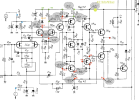
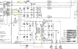
i've also measured the voltage test points around the power supply and everything there is green as per the first screenshot .

measurements start to look wrong as per the screenshot of the right channel (left channel is similar, so I've omitted the screenshot)
 

Attachments

  • Screen Shot 2023-12-08 at 10.16.32 AM.png
    Screen Shot 2023-12-08 at 10.16.32 AM.png
    262 KB · Views: 14
  • Screen Shot 2023-12-08 at 10.18.42 AM.png
    Screen Shot 2023-12-08 at 10.18.42 AM.png
    296.7 KB · Views: 14
Back
Top Bottom