
• The move to the new server is done. There are some software and database maintenance updates in process. This has us passing the hat around to help out. We appreciate any donations. Seriously, even a dollar helps. The payment page may be found here - https://www.audiokarma.org/support.html

Sansui Alpha series settings and notes

smurfer77

Super Member
Hi folks,

As we know, there are very few service manuals available for the Alpha series. This post is a kind of placeholder for Sansui alphas series data; mainly service manual adjustment data, but other points could be saved here too. I will edit this first post to have key data updated. If you have key service manual, adjustment, parts data, etc. post below and I will compile it for easy reference in this first post. I will throw in a couple of "B" series amps that are related although I may remove if it gets a bit messy.

Maybe those with the knowledge of the early alpha models with X equivalent models could fill us in on which models those are and if adjustments and SMs are out there?

BIAS volage, Emitter resistance, idle current
AU-Alpha507R/Alpha517R/x501: 6,6mV 0.22Ohm, 30mA (SM available)
AU x711: 5.5mV 0.22Ohm, 25mA
AU x911DG: 5.0mV 0.22Ohm, 23mA
AU x701/x901: 17.0mV 0.44Ohm, 39mA
or 8.5mV 0.22Ohm, 39mA

B-2102: 6.6mV 0.22Ohm, 30mA
B-2301/B-2201: 20mV 0.22Ohm, 90mA

AU-Alpha907DR: 8.8mV 0.22Ohm, 40mA (schematic only, no SM)

AU-Alpha907KX: 8.8mV 0.22Ohm, 40mA (SM avail, but no adjustments included that I can see, so I don't know where the 8.8mV came from, although it makes sense.)

AU-Alpha907XR: 8.8mV 0.22Ohm, 40mA (SM available)
AU-Alpha907limited: 28.6mV 0.22Ohm, 130mA (SM available)

AU Alpha607MR/MRX: 10mV 0.22Ohm, 45mA (SM available)
AU-Alpha707MR/MRX: 10mV 0.22Ohm, 45mA (SM available)
AU-Alpha907MR/MRX: 8.8mV 0.22Ohm, 40mA (SM available)

AU-Alpha907NRA: 8.8mV 0.22Ohm, 40mA

AU Alpha607NRAII: ? mV 0.22Ohm
(mine was 20-25mV, i set to 20mV (90mA))

DC offset:
Can wander around 50mV if you wait long enough. Do 'hot-to-cold' and 'hot-to-ground' steps simultaneously as they affect each other. As per manual, repeat bias and offset adjustment twice more.

Temperature:
There is a possibility that amp board on phono side sits a tiny bit (1-2C, not more) warmer than other side due to poorer thermal dissipation to chassis.

Other:
Don't ground negative ('cold' (inverting)), or positive ('hot' (non-inverting) speaker terminals accidentally with measurement devices such as a ground clip of scope probes that go to scope chassis. Both terminals are active contrary to conventional meaning of 'hot' and 'cold' in electronics.

MORE TO COME. Please add data below and I will update this first post.
 
Last edited:
Register to hide this ad
These are notes on the Alpha series which I have accumulated from AK postings with attributions when possible because I cannot vouch for there accuracy:

Output LAPT transistors from member richka August 28, 2013 http://www.audiokarma.org/forums/index.php?threads/sansui-au-07-info-request.472551/#post-7063300. What follows is a copy of his post.

this is what i have in my archive ;copied from this site

"""""During my intensive investigation, finally I found all things about Sansui amp of 1990's.

I'm posting this to share these infromations with anybody who may have similar problems.


Here what I found during my reseach in past 2 weeks

1. All Sansui amplifiers from 1990 uses transistors marked as LAPT-23 (TO-200 type), LAPT-3 and LAPT-2 (both TO-3P type). All are multiemiter-type devices, made by Sanken. If there's more than one alternative,
the choice is the transistor with most symettrical Ton/Toff and shortest Tstor, as all voltages are far over the supply voltage acrros the filter capacitors.

2. LAPT-23 are incorporated in flagship amps, carriyung the 907 number, irrespective of generations (DR, -KX, -XR, -MR and -NRA).
LAPT 23 are 2SA1216/2SC2922, 2SA1215/2SC2921, or 2SA1295/SC3264.
All are VERY similar 17A devices, but differ only in voltage (160V,180V and 230V respectively). The gain, Ton/Toff, linearity etc. are also similar. The first transistor is equivalent, the others being nearest solutions.

3. LAPT-3 are: 2SA1386/2SC3519 and 2SA1294/2SC3263. Both are 15A but 160V and 230V, respectively. The later are used by Accuphase amplifiers (flagship E-408), and the 3519 are used in almost all Sansui "707"
up to 1990.
Since the power supply is identical for all "707s" (on the international marked the last one was called AU-X901), I decided to go with these as first choice, and if not working properly, to change all outputs with 2SC3263/2SA1294.
(see below the confirmation from Sanken)

3. LAPT-2 remain to be equivalents for smaller models, "AU-@607", and for that reason it can be only 2SA1303/2SC3284 (14A/150V), by analogy of AU-X701 (which in Japanaise market is "AU-@607i"), and AU-X911DG,
which is again japanaise "607" model, but with dual mono design and thus using PCB F-6169 power amp board. This PCB is common for AU-@707DR too, and probably to other models.
For the older flagship amps, like AU-@907i or similar, there's usually 8 such devices per channel. I can speculate, this choice is probably due to very short Ton/Toff as this characteristic yields pleasant and natural sound.
For example, "valve-like" sound produced by MOSFETs is due to very short Ton/Toff swithiching meaning 10-20 time faster than bipolars.

And finally, today I received the confirmation from Sanken corp. that I was right in my assumptions, as LAPT-3 actually ARE equivalents of 2SC3519/2SA1386. So my above conclusions are valid, not a fiction.

That's all. Thank you very much to all you trying to help me. """

P.S. 07 Anniversary are NM-LAPT transistors :translate.google.com/translate?hl=en&sl=ja&tl=en&u=http%3A%2F%2Faudio-heritage.jp%2FSANSUI%2F

Last edited: Aug 28, 2013

Marc
 
Here are some of czubsi's deleted posts, The main point here being manual equivalence, i.e. 907 XR for 907 limited. What follows is from czubsi.


Official service of Sansui closed (June 2014). Sansui never has provided instruction alpha series !!! I got them, provided that they do not share ...


Unfortunately, I do not know the English language ... it would be easier to share information ...

some facts :


each Alpha Series model 907 is equivalent to the mosfet:

907i - 907i mos limited

907 L extra - B-2102 MOS Vintage, AU-X1111 MOS Vintage

907 DR / 907KX - B2103 MOS Vintage

907 XR - 907 limited

907 MR - B2105 MOS Vintage

907 NRA - did not manage to ...


Some facts about which you might not know ...


AU-07 is 907 MR (about 30 Riken more and weaker transformer, and a few minor differences - for example, another PCB ... the same as in the B2105 MOS Vintage !!! ...)

907liited is 907 XR (about 20 Riken more and weaker transformer and a few minor differences).

B2105 MOSVintage it AU-07 (about 8 Riken more + MOS FET transistor and stronger transformer)

MRX 907 is 907 MR (filtration Home !!! DR model and a larger capacity).

907 MR - 2 x 5600 uF

907 MRX - 2 x 8200 uF


AU-07 is better than 907 limited construction which but did not appreciate it highly because it is too expensive !!! This, however, my feelings. I AU07 :-)


Today, 06:56 AM

czubsi

AK Member


Join Date: Jan 2013

Posts: 88


Are you passionate about Sansui so? How do you understand? Sit at the keyboard and wait for something right down from the sky ???? You know why I got this material? Because the schema of the first 907i of the pictures he drew on amp8 !!!! photo paper mached front and rear plates and element by element I drew the diagram ... I sent it to check in return got the answer that I get these materials because I have a real passion ... Do you understand? You ask skippy like playing 907 limited .... so how was he to know that if the amplifier is BAD !!!! One channel is not playing and the other is totally out of tune ... He did not write about this ??? .... He asked me for help ... I gave him all the tensions at checkpoints with the scheme !!!! I did not hear even a thank you ...


To be fair you pass a voltage of 907 limited


I've included a few tensions at checkpoints:


between kR63-kC1 = 29,5 V

between kR7-kR5 = 22,0 V

between kR6-kC9 = 12,0 V

between kR7-kR8 = 12,0 V

between kR15-kQ2 = 28,0 V

between kR16-kQ3 = 28,0 V

between kR22-kQ4 = -28,0 V

between kR23-kQ5 = -28,0 V

between kR64-kC2 = -28,5 V

between kR17-kQ2 = 13,0 V

between kR18-kQ3 = 13,0 V

between kR20-kQ4 = 11,0 V

between kR21-kQ5 = 11,0 V

between kR31-kQ9 = -28,5 V

between kR30-kQ7 = 28,6 V

between kR29-kQ8 = -28,5 V

between kR28-kQ6 = 28,6 V

between kR43-kQ12 = 2,6 V

between kR43-kQ14 = -2,6 V

between kR44-kQ13 = 2,6 V

between kR44-kQ15 = -2,6 V

between kR46-kQ19 = -2,0 V

between kR46-kQ17 = 2,0 V

between kR45-kQ18 = -2,0 V

between kR45-kQ16 = 2,0 V

between kFT23-kFT27 = -29,5 V

between kFT22-kFT25 = -29,5 V

between kFT20-kFT24 = 29,5 V

between kFT21-kFT26 = 29,5 V


I wrote that with service manual au-x911 to set up each Sansui - it's true! In the manual tuning procedure it is the best I know - I use it all the next generation of amplifiers alpha or DR model! is the only sm are mentioned tuning preamplifier to cross main amplifier in positions minimum volume and maximum volume !!!! Of course currents rest for the model 907 = 8.8 mV !!!! (907DR, 907KX, 907XR, 907 MR and 907NRA = 8.8 mv !!!!!!!!!!!!)

Marc
 
Here are some of czubsi's deleted posts, The main point here being manual equivalence, i.e. 907 XR for 907 limited. What follows is from czubsi.


Official service of Sansui closed (June 2014). Sansui never has provided instruction alpha series !!! I got them, provided that they do not share ...


Unfortunately, I do not know the English language ... it would be easier to share information ...

some facts :


each Alpha Series model 907 is equivalent to the mosfet:

907i - 907i mos limited

907 L extra - B-2102 MOS Vintage, AU-X1111 MOS Vintage

907 DR / 907KX - B2103 MOS Vintage

907 XR - 907 limited

907 MR - B2105 MOS Vintage

907 NRA - did not manage to ...


Some facts about which you might not know ...


AU-07 is 907 MR (about 30 Riken more and weaker transformer, and a few minor differences - for example, another PCB ... the same as in the B2105 MOS Vintage !!! ...)

907liited is 907 XR (about 20 Riken more and weaker transformer and a few minor differences).

B2105 MOSVintage it AU-07 (about 8 Riken more + MOS FET transistor and stronger transformer)

MRX 907 is 907 MR (filtration Home !!! DR model and a larger capacity).

907 MR - 2 x 5600 uF

907 MRX - 2 x 8200 uF


AU-07 is better than 907 limited construction which but did not appreciate it highly because it is too expensive !!! This, however, my feelings. I AU07 :)


Today, 06:56 AM

czubsi

AK Member


Join Date: Jan 2013

Posts: 88


Are you passionate about Sansui so? How do you understand? Sit at the keyboard and wait for something right down from the sky ???? You know why I got this material? Because the schema of the first 907i of the pictures he drew on amp8 !!!! photo paper mached front and rear plates and element by element I drew the diagram ... I sent it to check in return got the answer that I get these materials because I have a real passion ... Do you understand? You ask skippy like playing 907 limited .... so how was he to know that if the amplifier is BAD !!!! One channel is not playing and the other is totally out of tune ... He did not write about this ??? .... He asked me for help ... I gave him all the tensions at checkpoints with the scheme !!!! I did not hear even a thank you ...


To be fair you pass a voltage of 907 limited


I've included a few tensions at checkpoints:


between kR63-kC1 = 29,5 V

between kR7-kR5 = 22,0 V

between kR6-kC9 = 12,0 V

between kR7-kR8 = 12,0 V

between kR15-kQ2 = 28,0 V

between kR16-kQ3 = 28,0 V

between kR22-kQ4 = -28,0 V

between kR23-kQ5 = -28,0 V

between kR64-kC2 = -28,5 V

between kR17-kQ2 = 13,0 V

between kR18-kQ3 = 13,0 V

between kR20-kQ4 = 11,0 V

between kR21-kQ5 = 11,0 V

between kR31-kQ9 = -28,5 V

between kR30-kQ7 = 28,6 V

between kR29-kQ8 = -28,5 V

between kR28-kQ6 = 28,6 V

between kR43-kQ12 = 2,6 V

between kR43-kQ14 = -2,6 V

between kR44-kQ13 = 2,6 V

between kR44-kQ15 = -2,6 V

between kR46-kQ19 = -2,0 V

between kR46-kQ17 = 2,0 V

between kR45-kQ18 = -2,0 V

between kR45-kQ16 = 2,0 V

between kFT23-kFT27 = -29,5 V

between kFT22-kFT25 = -29,5 V

between kFT20-kFT24 = 29,5 V

between kFT21-kFT26 = 29,5 V


I wrote that with service manual au-x911 to set up each Sansui - it's true! In the manual tuning procedure it is the best I know - I use it all the next generation of amplifiers alpha or DR model! is the only sm are mentioned tuning preamplifier to cross main amplifier in positions minimum volume and maximum volume !!!! Of course currents rest for the model 907 = 8.8 mV !!!! (907DR, 907KX, 907XR, 907 MR and 907NRA = 8.8 mv !!!!!!!!!!!!)

Marc

Thanks Marc. You saved me from sharing the LAPT post... that one is gold. All else I have on those is
" Of special interest to audio engineers is Sanken's LAPT (Large Area Parallel Transistor) line which use multiple thermally-coupled transistors in parallel. The result is composite transistors that maintain their excellent linear gain characteristics even at full output current, and provide extended frequency response, typically to 40MHz. Best of all, however, is their extraordinary resistance to secondary breakdown. No other audio transistor can match Sanken for power handling at over 100V!" Sorry I can't remember where that is from. Also some links related to possible substitutes:
https://www.profusionplc.com/brands/sanken
http://www.semicon.sanken-ele.co.jp/en/index.html
http://www.semicon.sanken-ele.co.jp/ctrl/en/product/list/Audio/

I will add the 8.8mV bias voltage for the 907DR/KX/NRA from the Czusbi last line ("Of course currents rest for the model 907 = 8.8 mV !!!! (907DR, 907KX, 907XR, 907 MR and 907NRA = 8.8 mv !!!!!!!!!!!!)") to the main page. Thanks again!

Okay a crazy question/theory for everyone: My Alpha607NRAII has the same (or almost the same) power board as my 607MR, but with a bunch of parts missing since doesn't need much of the other voltage regulation/supply as it actually has a separate transformer for preamp etc, hidden up front.
au-alpha607nraii(2).JPG

It's quite clear that squeezing this transformer up in the front panel meant the volume knob had to be moved off centre compared to MR series. However, looking at the NRA series, they already had the volume knob stranglely off centre. Have look here at https://audio-database.com/SANSUI/amp/index.html and scroll down to see the volume knob shift to the right hand side, wildly off-centre as we move from MR to NRA series. So the crazy question is, do you think it possible that Sansui intended either NRAs to have the preamp transformer, perhaps that there would be 707NRAII and 907NRAII and they were just getting the 'tooling'/parts ready for that transformer to squeeze in the later model.
 
Here are some of czubsi's deleted posts, The main point here being manual equivalence, i.e. 907 XR for 907 limited. What follows is from czubsi.


Official service of Sansui closed (June 2014). Sansui never has provided instruction alpha series !!! I got them, provided that they do not share ...


Unfortunately, I do not know the English language ... it would be easier to share information ...

some facts :


each Alpha Series model 907 is equivalent to the mosfet:

907i - 907i mos limited

907 L extra - B-2102 MOS Vintage, AU-X1111 MOS Vintage

907 DR / 907KX - B2103 MOS Vintage

907 XR - 907 limited

907 MR - B2105 MOS Vintage

907 NRA - did not manage to ...


Some facts about which you might not know ...


AU-07 is 907 MR (about 30 Riken more and weaker transformer, and a few minor differences - for example, another PCB ... the same as in the B2105 MOS Vintage !!! ...)

907liited is 907 XR (about 20 Riken more and weaker transformer and a few minor differences).

B2105 MOSVintage it AU-07 (about 8 Riken more + MOS FET transistor and stronger transformer)

MRX 907 is 907 MR (filtration Home !!! DR model and a larger capacity).

907 MR - 2 x 5600 uF

907 MRX - 2 x 8200 uF


AU-07 is better than 907 limited construction which but did not appreciate it highly because it is too expensive !!! This, however, my feelings. I AU07 :)


Today, 06:56 AM

czubsi

AK Member


Join Date: Jan 2013

Posts: 88


Are you passionate about Sansui so? How do you understand? Sit at the keyboard and wait for something right down from the sky ???? You know why I got this material? Because the schema of the first 907i of the pictures he drew on amp8 !!!! photo paper mached front and rear plates and element by element I drew the diagram ... I sent it to check in return got the answer that I get these materials because I have a real passion ... Do you understand? You ask skippy like playing 907 limited .... so how was he to know that if the amplifier is BAD !!!! One channel is not playing and the other is totally out of tune ... He did not write about this ??? .... He asked me for help ... I gave him all the tensions at checkpoints with the scheme !!!! I did not hear even a thank you ...


To be fair you pass a voltage of 907 limited


I've included a few tensions at checkpoints:


between kR63-kC1 = 29,5 V

between kR7-kR5 = 22,0 V

between kR6-kC9 = 12,0 V

between kR7-kR8 = 12,0 V

between kR15-kQ2 = 28,0 V

between kR16-kQ3 = 28,0 V

between kR22-kQ4 = -28,0 V

between kR23-kQ5 = -28,0 V

between kR64-kC2 = -28,5 V

between kR17-kQ2 = 13,0 V

between kR18-kQ3 = 13,0 V

between kR20-kQ4 = 11,0 V

between kR21-kQ5 = 11,0 V

between kR31-kQ9 = -28,5 V

between kR30-kQ7 = 28,6 V

between kR29-kQ8 = -28,5 V

between kR28-kQ6 = 28,6 V

between kR43-kQ12 = 2,6 V

between kR43-kQ14 = -2,6 V

between kR44-kQ13 = 2,6 V

between kR44-kQ15 = -2,6 V

between kR46-kQ19 = -2,0 V

between kR46-kQ17 = 2,0 V

between kR45-kQ18 = -2,0 V

between kR45-kQ16 = 2,0 V

between kFT23-kFT27 = -29,5 V

between kFT22-kFT25 = -29,5 V

between kFT20-kFT24 = 29,5 V

between kFT21-kFT26 = 29,5 V


I wrote that with service manual au-x911 to set up each Sansui - it's true! In the manual tuning procedure it is the best I know - I use it all the next generation of amplifiers alpha or DR model! is the only sm are mentioned tuning preamplifier to cross main amplifier in positions minimum volume and maximum volume !!!! Of course currents rest for the model 907 = 8.8 mV !!!! (907DR, 907KX, 907XR, 907 MR and 907NRA = 8.8 mv !!!!!!!!!!!!)

Marc

PS. I had seen those comments about the 907LTD and AU-07 having similar design to other models but with 'weaker transformer'. I have some doubts about the that without further evidence. I may seem a logical leap that because of the rated 80W or so for the 907LTD and AU-07 a downgraded power transformer was used, but the power transformer in the 907LTD weighs 13kg, the same as in the 907XR which to me indicates the transformer is of same pedigree.
 
PS. I had seen those comments about the 907LTD and AU-07 having similar design to other models but with 'weaker transformer'. I have some doubts about the that without further evidence. I may seem a logical leap that because of the rated 80W or so for the 907LTD and AU-07 a downgraded power transformer was used, but the power transformer in the 907LTD weighs 13kg, the same as in the 907XR which to me indicates the transformer is of same pedigree.


Hi David,

The 907 Limited was a MOS FET amplifier and for reasons beyond me these were all low power output amplifiers. The AU-07 was not. Both amplifiers, given the dynamic power output ratings down to 2 Ohms, must have been designed to handle high current output, though I wouldn’t dare test them on 2 Ohm speakers like some of the Infinities. The real mystery to me is why the AU-07 was designed to have such a low power rating.

Marc
 
Hi David,

The 907 Limited was a MOS FET amplifier and for reasons beyond me these were all low power output amplifiers. The AU-07 was not. Both amplifiers, given the dynamic power output ratings down to 2 Ohms, must have been designed to handle high current output, though I wouldn’t dare test them on 2 Ohm speakers like some of the Infinities. The real mystery to me is why the AU-07 was designed to have such a low power rating.

Marc

I had a theory on that. I suspect the reason for the low power ratings is related to that they liked to run highish idle current on special models. This both adds burden to the power supply but also there is the question of thermal management. The 907LTD already sits at 50-55C at idle, and perhaps the driver stage was dialed-back as 80-100W is all the heat sinking can handle and maintaining stable/safe operation.

We will have to wait until we know AU-07 bias settings, but I suspect it also runs highish idle. Does yours run warm?
 
The bias setting is 8,8mV like in most of the bipolar 907's
if any one want to know anything from AU-07 service manual feel free to ask me about details

Thanks for this information. Could you please confirm the emitter resistor value, so we can compare idle current to other 907 models ?
 
Great info guys, thanks!

Regarding the transformer differences:
PS. I had seen those comments about the 907LTD and AU-07 having similar design to other models but with 'weaker transformer'. I have some doubts about the that without further evidence. I may seem a logical leap that because of the rated 80W or so for the 907LTD and AU-07 a downgraded power transformer was used, but the power transformer in the 907LTD weighs 13kg, the same as in the 907XR which to me indicates the transformer is of same pedigree.

Looking at the service manual for the a907XR and the a907LTD, they do use different part numbers. And looking at the schematics, this is confirmed: AC output voltages are lower for the LTD, 42 Volts vs 55V for the XR. So this would fit the picture of lower output and keeping thermal management in control, as Smurfer77 suggested. (Bias for the a907LTD is 28.6mV +-1mV).
It would be interesting to compare these to some other MOS-FET models. I only have info for the X1111 MOS/B2102 MOS and B-2105 MOS.
These have a transformer output voltage of 47 Volts, bias setting of 27mV +-2 with a power output of 110W rms into 8Ohms and 150W/6Ohms. So again different transformers for each model. Output power for the LTD could be traded for greated linearity and improved sound quality. Any differences would be minor I guess.
 
Great info guys, thanks!

Regarding the transformer differences:


Looking at the service manual for the a907XR and the a907LTD, they do use different part numbers. And looking at the schematics, this is confirmed: AC output voltages are lower for the LTD, 42 Volts vs 55V for the XR. So this would fit the picture of lower output and keeping thermal management in control, as Smurfer77 suggested. (Bias for the a907LTD is 28.6mV +-1mV).
It would be interesting to compare these to some other MOS-FET models. I only have info for the X1111 MOS/B2102 MOS and B-2105 MOS.
These have a transformer output voltage of 47 Volts, bias setting of 27mV +-2 with a power output of 110W rms into 8Ohms and 150W/6Ohms. So again different transformers for each model. Output power for the LTD could be traded for greated linearity and improved sound quality. Any differences would be minor I guess.

In the quoted passage, I wrote that the weight is the same, indicating its the same pedigree, not that the transformer is the same part. Yes, the transformer voltage for the output rails are lower, in keeping with the mentioned lower output power.

Bias on all of the MOSFET models is typically relatively high compared to most of BJT models, not just for Sansui but in general. This is because designers wish to avoid (in addition crossover distortion common to BJTs as well A/B scheme) higher (than BJT) non-linearity that occurs for MOSFETs at small amplitude/bias (confirmed by conversation with Nelson Pass).
 
Thanks @smurfer77 for your additional explanation; did not mean to contradict you of course. I am impressed that you are on speaking terms with Mr. Pass, whose designs and minimalistic engineering approach I hold in high respect.
Douglas Self provides some info on MOSFET power stages in his book on amplifier design, but no specifics on bias settings. He does not seem to see many benefits in them over BJTs - on theoretical grounds at least. Anyway, I am very happy with my B2102 MOS and actually prefer its sound over the older Sansuis. Very curious to compare it to the 907 Limited!
 
Thanks @smurfer77 for your additional explanation; did not mean to contradict you of course. I am impressed that you are on speaking terms with Mr. Pass, whose designs and minimalistic engineering approach I hold in high respect.
Douglas Self provides some info on MOSFET power stages in his book on amplifier design, but no specifics on bias settings. He does not seem to see many benefits in them over BJTs - on theoretical grounds at least. Anyway, I am very happy with my B2102 MOS and actually prefer its sound over the older Sansuis. Very curious to compare it to the 907 Limited!

Ha. You are very welcome to contradict me. This is a forum for discussion and I take no offense. And I hope my tone in reply also does not provide offense. I'm rather direct sometimes. I'm not close to Nelson, but I do bump into him now and again... I doubt he knows my name. He is very approachable... as are many truly great people in my experience. (it's the not so great people, insecure about their knowledge, who tend to make themselves less approachable).
 
To Alfanjis

I too would be interested in a comparison of the B-2102MV and the 907 Limited. The B-2102MV was the amplifier end of the AU X1111MV and these two MOS FET amplifiers are separated by about 6 years and, IIRC, were the last two of Sansui’s MOS FET integrateds. How the B-2102MV sounds, however, might be significantly influenced by which preamplifier you are using to drive it. Regards to all.

Marc
 
Thanks for the wonderful topic.

I'm having a hard time to adjust DC offset on my Alpha 607 MOS Premium... one channel is ~70mV and the other close to 0mV.

I did not find the service manual for this specific model so I used the one for the 607MR. Terminals and adjustment points are all in the same position so I followed the instructions to get to DC Offset, tried to adjust both jVR5L and jVR5R but it does not effect my DC offset readings, my probe shows exactly the same results no matter I try to adjust these two adjustment points... Of course I'm doing something wrong and now the situation is even worst :(

Someone said here TO NOT ground COLD and HOT terminals for DC offset readings as they are all alive BUT this is exactly what Sansui SM is suggesting to do... See picture below for reference. Am I reading it wrongly or the Japanese/English translation is wrong ? It says: Connection HOT OUT Speaker terminal and COLD OUT Speaker terminal

Another intriguing point: It says on "Remarks" Input Selector "CD" - OK very obvious - and then Input Terminal "Short" o_O What does it mean ? That I have to short circuit the respective CD input RCA connector while I measure DC Offset ?
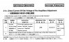
DC Offset pre-amp
SM 607MR DC Offset.JPG

Take a look at this too:
On the "DC Offset Main Amp" instructions, "Step 2" - "Cold Side" - it says "connect probes between COLD OUT Speaker terminal and... COLD OUT Speaker terminal" :confused: This is not correct...


DC Offset Main Amp
SM 607MR DC Offset II.JPG


Guys, I'm in need of some help here and any light is welcome. Can you help me on how to adjust this integrate? BIAs, Offsets and their values, please keep in mind this is also a MOSFET sansui.

Thank you,

Sartore
 
First of all, do dc offset measurments directly on power amp hot/cold pins.

1st do power amp settings with operation set to balanced inputs and vol set to minimum
2nd do preamp settings with operation set to cd, shorted cd inputs and vol to minimum, set kvr5 for both channels, if it will allow you to adjust correctly, confirm offset with vol set to half and then to max.

Next do hot/ground adjustments with again operatiin set to balanced and vol on minimum.

Next adjust bias for 27mV in both channels and again do offset measurments / adjustments
 
First of all, do dc offset measurments directly on power amp hot/cold pins.

1st do power amp settings with operation set to balanced inputs and vol set to minimum
2nd do preamp settings with operation set to cd, shorted cd inputs and vol to minimum, set kvr5 for both channels, if it will allow you to adjust correctly, confirm offset with vol set to half and then to max.

Next do hot/ground adjustments with again operatiin set to balanced and vol on minimum.

Next adjust bias for 27mV in both channels and again do offset measurments / adjustments

Thank you! Stupid question: what do you mean by shorted cd inputs ?
 
Back
Top Bottom