Hello, did you solve the power amp issue or still not working ?Many thanks to all on helping with this project. I have learned so much about repairing these vintage units!
I have decided to end this project and just keep the parts for people who need them or maybe for a project I do in the future.
If my experience can ever help someone, as a new person to more complex repairs here's what I have learned:
Again, thanks to all that helped.
- NEVER, EVER, replace components on mass, as a process of elimination, or as a troubleshooting process. If you start down this path, there is very likely no road back. In my case I ended up putting many good original components back in and because the circuit board was old the soldering pads started to break.
- Use and trust the DBT. This was the best advise from this group and I will use my DBT faithfully on future projects.
- Be careful adjusting the bias current before or as part of resolving issues. This is a very sensitive setting and can cause all sorts of "changes" which made troubleshooting for me more difficult.
- Read the experts responses carefully! In many cases, i read the first sentence in a response and started to work on that ignoring other information provided. (I really picked up on this when I went back over the entire thread as a post -mortem on my project.)
- Be very careful about testing the correct orientation of transistors prior to insertion. I ended up buying (sadly too late) a cheap component tester which worked great.
- Persistence is a double edged sword. While generally a good asset, sometimes we go beyond capabilities and experience and spend way too much time and money on a project. In my case, this project while not successful in reviving the amp, taught me all of above for the next project!!!!
If anyone needs parts for an AU series Sansui Amp, I will be happy to oblige.
Cheers
Cam


You are using an out of date browser. It may not display this or other websites correctly.
You should upgrade or use an alternative browser.
You should upgrade or use an alternative browser.
Sansui AU-6900 Woes .......
- Thread starter camgilbert
- Start date

Njau
New Member
Hello All. I m writing from Kenya . Having acquired a Sansui-AU6900 last year, i only hooked it up last month with lots of excitement. Prior to this , it was in storage. I hooked up KEF Eggs (6 Ohms) on Channel B and Jamo Set ( 8 Ohms) on Channel A. The reproduction was super- but i never did more than half the volume on this day. Unfortunately i only enjoyed the sound on the one day only and family reported that the speakers were spitting out scarery noises. Next day the Amp powered up okay but no sound. So for the last few weeks i have been contemplating taking the amp to a technician but i have now chickened out and want to do it myself as the first ever project. No electronics background but can understand the language and do the work. I have a multimeter . So today i opened up the thing-. Measured 2 obvious caps and reading are crazy. Pulled out another shaky cap and readings too don't look good. The 7A Fuses F601 and F602 are blown. At this rate i will pull out everything and probably regret. So i have applied the breaks, Joined Audiokarma and now seek to be welcomed with guidance. In the place of the AU6900 i have replaced with Cambridge A5 and these two are totally different. How can i get this kid playing?
Attachments


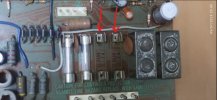


The Fuxtor
Addicted Member
You've probably got blown output transistors. Those caps might be bad but they won't blow your fuses. Test your transistors and maybe the main rectifier. I'm guessing the 2 sets of speakers gave the amp a bigger impedance load then it's rated for and blew a channel.
Good Luck. The AU 6900 is a difficult amp to start the hobby with. It is worth getting fixed one way or another. (I presume you have downloaded the service manual for the AU-7900 available on this site). If it has been in storage (for years?) your problems could be more complex. Welcome aboard BTW.
Njau
New Member
Your guidance is well appreciated. So i have tested the output transistors - Four on one side and another 4 on the other side. There seem to be good readings from 4 of one side and a bad reading from 4 of the other side. Could this indicates a problem on one side? Remember the 3 caps are still out. Also tell me which is the "Main Rectifier"You've probably got blown output transistors. Those caps might be bad but they won't blow your fuses. Test your transistors and maybe the main rectifier. I'm guessing the 2 sets of speakers gave the amp a bigger impedance load then it's rated for and blew a channel.
Attachments

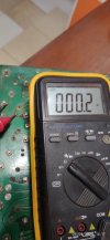
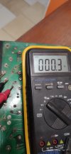


Njau
New Member
Thank for the encouragement. Is the AU-7900 the closets or the AU-7700? Do you have a link for the 7900?Good Luck. The AU 6900 is a difficult amp to start the hobby with. It is worth getting fixed one way or another. (I presume you have downloaded the service manual for the AU-7900 available on this site). If it has been in storage (for years?) your problems could be more complex. Welcome aboard BTW.
Njau
New Member
Where are the Fuse Resistors. I feel like i want to have spares for all of them. Are the many? Why does this smell like the source of my problem?Not forgetting the fuse resistors that go high resistance 'at the drop of a hat' on these amplifiers, and mess up the DC conditions so badly that they cease to function correctly.
Njau
New Member
Are these correct? # R 31, R 32, R 41 and R 42Where are the Fuse Resistors. I feel like i want to have spares for all of them. Are the many? Why does this smell like the source of my problem?

Yes, correct - sorry I didn't see your post until just now. Just replace them with ordinary Metal Film or Metal Oxide replacements, not new fuse resistors, or you'll just be replacing them again in a short while.Are these correct? # R 31, R 32, R 41 and R 42
 The 'rule of thumb' is to use the same wattage replacements - they are safety components, so you want them to burn and open if there is a serious fault, making them higher wattage will make them last longer before they open - not what you want.
Last edited:
Njau
New Member
Well noted. So does it mean at the end of the project i will replace all the four with genuine ones?Yes, correct - sorry I didn't see your post until just now. Just replace them with ordinary Metal Film or Metal Oxide replacements, not new fuse resistors, or you'll just be replacing them again in a short while.
No, replace them once and leave them there - 220Ω, ¼ watt Metal Film recommended. All new resistors are flameproof, and will burn and open nicely if over stressed by a fault.Well noted. So does it mean at the end of the project i will replace all the four with genuine ones?
Njau
New Member
Now i have even come across cracked Resistor R612 -R613 . I want to remove it and measure it. Just zoom and you will see 2 cracksWell noted. So does it mean at the end of the project i will replace all the four with genuine ones?
Attachments

Njau
New Member
R612 measures OL and R613 measures 8Kohms. and 601 measures 2.18Kohms. From these measures only R601 looks okay to me.Now i have even come across cracked Resistor R612 -R613 . I want to remove it and measure it. Just zoom and you will see 2 cracks
When the AU-6900 was released, it was accompanied by the AU-5900 and its bigger brother the AU-7900.
All three are based on the same AU-7900 design architecture. The 5900 and 6900 being scaled down simplified versions of the 7900.
Sansui issued one service manual for all three. I thought it was available in our library. But I couldn't find it.
I tried attaching the pdf file I downloaded from elsewhere but it is too big.
Google online the service manual for the AU-7900. [Edit] Try https://www.manualslib.com/products/Sansui-Au-7900-3721731.html
[Edit 2] Here it is: https://akdatabase.com/AKview/displayimage.php?album=28&pos=143 It is on page 8 of the akdatabase service manuals and documents.
Last edited:
Njau
New Member
Thank you very much. Got the download. This will help me navigate thru this repair projectWhen the AU-6900 was released, it was accompanied by the AU-5900 and its bigger brother the AU-7900.
All three are based on the same AU-7900 design architecture. The 5900 and 6900 being scaled down simplified versions of the 7900.
Sansui issued one service manual for all three. I thought it was available in our library. But I couldn't find it.
I tried attaching the pdf file I downloaded from elsewhere but it is too big.
Google online the service manual for the AU-7900. [Edit] Try https://www.manualslib.com/products/Sansui-Au-7900-3721731.html
[Edit 2] Here it is: https://akdatabase.com/AKview/displayimage.php?album=28&pos=143 It is on page 8 of the akdatabase service manuals and documents.
Keep us posted.
I have a AU-7900 which I love, but I had weird troubles with it for years that a lot of repair technicians couldn't fix. That is why I say this is a difficult series of amps to work on and diagnose, so this one may stay on your workbench for a while. I like both the look and the features of this era. Cheers.
I have a AU-7900 which I love, but I had weird troubles with it for years that a lot of repair technicians couldn't fix. That is why I say this is a difficult series of amps to work on and diagnose, so this one may stay on your workbench for a while. I like both the look and the features of this era. Cheers.
Njau
New Member
That's encouraging. It will be good for me cos i want to understand this amp. I plan to keep it and it would just serve me right to put it together myself.Keep us posted.
I have a AU-7900 which I love, but I had weird troubles with it for years that a lot of repair technicians couldn't fix. That is why I say this is a difficult series of amps to work on and diagnose, so this one may stay on your workbench for a while. I like both the look and the features of this era. Cheers.
But read this thread. It was started in August 2017 by a guy who had issues with his AU-6900. He had many frustrating experiences with it being his first major restore project. He threw in the towel on the project admitting defeat in January 2018. Post 119. and we haven't heard from him since 2018.
What I am implying is that this type of amp could be a widow maker (I.e. from the point of view of Electronics repair).
There is a lot of information in this website, and I am sure there is a lot to learn. The fellows who have responded to you so far are quite expert.
What I am implying is that this type of amp could be a widow maker (I.e. from the point of view of Electronics repair).
There is a lot of information in this website, and I am sure there is a lot to learn. The fellows who have responded to you so far are quite expert.