• The move to the new server is done. There are some software and database maintenance updates in process. This has us passing the hat around to help out. We appreciate any donations. Seriously, even a dollar helps. The payment page may be found here - https://www.audiokarma.org/support.html

Sansui AU-717 Restoration and Upgrade

Connor G

Ear conditioned
Subscriber
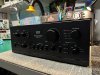
Hello fellow AKers! I just finished a comprehensive restoration of a beautiful Sansui AU-717. This thread is dedicated to showcase the steps I took during the restoration process. There will also be a video posted to my YouTube Channel showcasing the work I did there. Once it is uploaded, I will link it to this thread!

Preface:

Last week, I received a gorgeous Sansui AU-717 from a friend of mine for a top to bottom restoration.
Having around five years of experience working on audio gear, I have somehow managed to never work on a single Sansui integrated amplifier thus far. That being said, I can say with great certainty that this AU-717 was definitely a treat to work on!


Overview of work to be done:

The AU-717 will require a fairly straightforward, yet comprehensive restoration. It suffers from many of the same issues that similar amplifiers of this era do. Issues like bad soldering and corrosive glue are here in spades. Old capacitors, dirty switches and potentiometers, carbonized relay contacts, crusty adjustment trimmers, messy wave soldering flux residue... You get the idea. All of these issues need to be addressed to assure the stable working condition of this amplifier for the next few decades. Like I said before... comprehensive.

A small rant about the misnomer of a "restoration":

One of my biggest pet peeves in the audio world is the common practice of dramatizing work done to audio gear. This is usually done to artificially and disingenuously drive the price of gear on the second hand market up. Many people believe that a "restoration" only includes spraying deoxit into the potentiometers, cleaning the faceplate, blowing dust bunnies out of said piece of equipment, and less frequently, a basic recap. This is very far from the truth, and usually puts honest technicians like myself in a bad spot when confronted about why it takes as long as it does for a thorough restoration. Audio gear of this age suffers from much more than the typical bad capacitors, and usually requires specialized service to guarantee the stability of the unit overtime. Again, the term comprehensive servicing comes into play again. Remember this.

What I believe a "restoration" is:

In my eyes, a restoration is where a piece of equipment is brought back to factory specifications and working condition (or better) both inside and out. This is accomplished by addressing every issue both known and observed. Things such as removing corrosive glue, reflowing and defluxing circuit boards, replacing capacitors and known problematic signal transistors, regulators, diodes, and addressing heat related issues such as PCB and trace damage, remounting outputs and drivers on new thermal interfaces, and even a thorough cleaning. There are more steps to take than this, especially depending on what it is to be worked on, but you get the idea. There is much more to a "restoration" than what most eBay sellers would lead you to believe.


Getting back to the topic at hand: The Sansui AU-717:

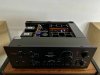
When I received the AU-717, It was in great shape. It arrived with it's original box and packing material, as well as it's owners manual. There was hardly a mark on the amplifier itself, which shows just how little use this amplifier has had throughout it's life - This will become ever more evident as this thread unfolds.
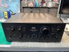
photo_2023-03-29_22-47-05.jpg

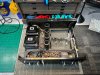
I started the restoration process as I usually do; Open the amplifier, inspect for damage, and bring it up on a variac to ensure all voltages are correct and that it comes out of protect. In this case, I found nothing wrong. The amplifier came right up and sprung to life. It came out of protection mode, and I was able to pass a signal through every stage of the amplifier. No excess heat or current draw :thumbsup:

photo_2023-03-29_22-56-38.jpg photo_2023-03-29_22-56-41.jpg photo_2023-03-29_22-56-40.jpg photo_2023-03-29_22-56-42.jpg photo_2023-03-29_22-56-43.jpg
photo_2023-03-29_22-56-46.jpg photo_2023-03-29_22-56-44.jpg photo_2023-03-29_22-47-09.jpg photo_2023-03-29_22-47-10.jpg


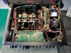
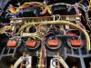
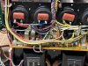
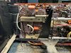
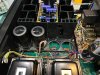
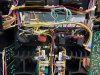
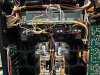
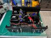
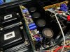
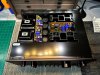
As you can see from these photos, This unit is even in great shape internally. Like I said, this amplifier has had very little use throughout it's life, so there is no heat stressed boards, leaking capacitors causing a mess, or even any physical damage. It is a great candidate for a restoration :)

Continued in the next post...
 
Last edited:
Register to hide this ad
Starting work:

After verifying the working condition of this amplifier in its current state when arriving to me, I began work. Starting with disassembly, I removed the power supply, both amplifier modules including respective heatsinks, and the phono equalizer / input board. This was a relatively straightforward process, minus the power supply. The amplifier modules had pin connectors that slid off of their respective posts quite easily. After removing them and four screws per module, the heatsink assembly pulled straight out of the amplifier.

photo_2023-03-29_22-47-11.jpg

After removing the amplifier modules, it was time to turn my attention to the power supply. This was a bit of a challenge, as every wire that leads to it had to be desoldered. What made it easier was the fact that Sansui opted to use "snap-in" pins at the end of each wire. This made it so the wires didn't fray when removed. A nice touch by Sansui, I must say. I see many people work around the wires and leave the power supply hanging from the amplifier chassis, but I found removing the entire board was the easiest route to take. No fighting with a rats nest of wiring with the possibility of causing damage with a loose hanging circuit board...

photo_2023-03-29_23-09-26.jpg photo_2023-03-29_23-09-28.jpg photo_2023-03-29_23-09-28 (2).jpg photo_2023-03-29_23-09-29.jpg photo_2023-03-29_23-09-30.jpg

photo_2023-03-29_23-09-31.jpg

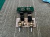
After getting the power supply out of the way, I focused my attention to the phono equalizer / input board. This one was pretty straightforward. Desolder a few wires (actually, many wires, as there are four ribbon cables attached to this board that lead to the circuit board that houses the RCA jacks), remove a few molex connectors, and detach the two axel shafts that lead to the switches. (I ended up removing the "C" clips that capture the axel shafts to the faceplate. This allows them to slide forward and away from the switch assemblies). After this, there are six screws that I removed in order to lift the board straight up and out.

photo_2023-03-29_23-15-51.jpg photo_2023-03-29_23-15-58.jpg

photo_2023-03-29_23-15-56.jpg
 
Last edited:
Amplifier modules:

The amplifier modules are very straightforward. The circuit board is screwed to the heatsink via a bracket. Wires lead from the circuit board to the TO-3 sockets, where the TO-3's are then mounted. The amplifier modules in this 717 were in great shape, minus the corrosive glue of course. That being said, they still required a lot of work.

photo_2023-03-29_22-47-25 (2).jpg

photo_2023-03-29_22-47-27 (2).jpg photo_2023-03-29_22-47-26.jpg photo_2023-03-29_22-47-28.jpg photo_2023-03-29_22-47-28 (2).jpg photo_2023-03-29_22-47-17.jpg photo_2023-03-29_22-47-27.jpg

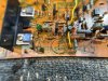
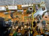
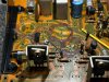
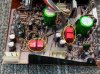
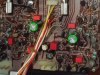
As you can see, the typical "old amp" issues can be found here. Corrosive glue eating away at components, cold solder joints, messy flux, bad capacitors, out of tolerance fusible resistors, and potentially noisy signal transistors. All of this has to be done away with. These issues, while not currently causing trouble, will surely wreak havoc if left alone.
 
Last edited:
Amplifier module(s) restoration:

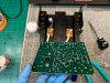
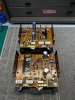
After breaking down both amplifier modules, I began work. Firstly, cleaning the dust and dirt off of each board. After careful cleaning and inspection, I removed old components and began scraping the corrosive glue. (See photos in post above). This process takes the longest out of everything, but is sped up with the use of Toluene to help break the glue down. After removing the glue, I found multiple areas of corrosion. All parts affected by this glue were replaced. This mainly includes small axial components like diodes and resistors that sit close to the board with exposed leads. After replacing all corrosion damaged components, I recapped both amplifier modules, replaced many fusible resistors, replaced the voltage reference zener diodes, replaced many TO-92 signal transistors, remounted the drivers and outputs on new silicone thermal pads, replaced the old trimmers with new Bourns equivalents, and finally reflowed and defluxed both circuit boards. The finished product looks perfect and will last many years.

photo_2023-03-29_22-47-18.jpg photo_2023-03-29_22-47-19.jpg photo_2023-03-29_22-47-20.jpg photo_2023-03-29_22-47-20 (2).jpg
photo_2023-03-29_22-47-23.jpg photo_2023-03-29_22-47-22.jpg photo_2023-03-29_22-47-21.jpg photo_2023-03-29_22-47-24.jpg
photo_2023-03-29_22-47-32.jpg
photo_2023-03-29_22-47-33.jpg


Only the highest quality parts being used, which is the same for every one of my restorations. I am a firm believer that if you don't use good parts, you aren't a good technician. End of story.
 
Last edited:
Power supply:

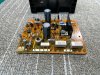
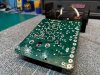
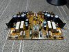
After finishing the amplifier modules, I turned my attention to the power supply. The power supply had a liberal amount of corrosive glue used on the large capacitors, which made the job very difficult. Lots of corrosion damaged parts, including two zener references that had their legs completely eaten through(!!!) - There are tons of capacitors, transistors, resistors, and diodes that need to be replaced here. The factory wave soldering was also abysmal, requiring a full rework and deflux.

photo_2023-03-29_22-47-35.jpg photo_2023-03-29_22-47-34 (2).jpg photo_2023-03-29_22-47-34.jpg photo_2023-03-29_22-47-37.jpg
photo_2023-03-29_22-47-37 (2).jpg photo_2023-03-29_22-47-39.jpg photo_2023-03-29_22-47-38.jpg photo_2023-03-29_22-47-38 (2).jpg

photo_2023-03-29_22-47-33 (2).jpg

photo_2023-03-29_22-47-36.jpg
 
Power supply restoration and upgrade:

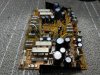
After spending some time removing all of the capacitors and associated glue, I inspected all components for signs of corrosion. To my dismay, there were many that suffered the green death from the nasty glue used. I yanked all damaged parts out and replaced with new. After that mess was dealt with, I began the normal procedure of recapping the board, replacing most semis in the power supply including the regulator transistors and rectifier diodes, installing a new relay, as well as reflowing the back of the board and removing all of the nasty flux to expose the beautiful artwork hidden underneath -- I even went as far as to polish the fuses and fuse holders too :D
Many capacitors on this board were upped in value to provide better filtering for associated stages of the amplifier.

photo_2023-03-29_22-47-43.jpg photo_2023-03-29_22-47-42.jpg photo_2023-03-29_22-47-41 (2).jpg photo_2023-03-29_22-47-40 (2).jpg photo_2023-03-29_22-47-44.jpg

photo_2023-03-29_22-47-41.jpg

photo_2023-03-29_22-47-43 (2).jpg
 
Last edited:
Power supply and amplifier module reinstallation and filter capacitor replacement:

After getting the amplifier modules and power supply completed, I decided to reinstall them into the amplifier and do some testing to make sure I didn't royally screw anything up ;)

Great news as everything came up perfectly and I achieved proper rail voltages, bias, and offset on each channel! Not to mention a healthy output from both channels :thumbsup:

photo_2023-03-29_22-47-44 (2).jpg

After testing the amplifier, I decided it was time to remove and replace the tired filter capacitors and associated polyester film bypass caps with new Kemet filter caps and polypropylene bypass capacitors. The new Kemet filter capacitors have the same outside diameter, so they fit into place with the original brackets perfectly. Their smaller height will allow for better airflow, too!

photo_2023-03-29_22-47-45.jpg photo_2023-03-29_22-47-46.jpg photo_2023-03-29_22-47-46 (2).jpg photo_2023-03-29_22-47-47.jpg photo_2023-03-29_22-47-49.jpg photo_2023-03-29_22-47-48.jpg

photo_2023-03-29_22-47-47 (2).jpg
 
Phono equalizer / input board restoration:

Okay so you will have to forgive me as I forgot to take "before" photos of this board. I was excited to dig into it and totally dropped the ball. Just imagine another tired circuit board with lots of parts that need replacement, and a disgusting wave soldering job that also needs to be redone.

This board took a while, as I had to gain match many signal transistors. Times like this are when I kick myself for not gain matching transistors beforehand :confused:

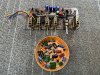
Lots of capacitors, resistors, signal transistors -- and how could I forget? There were four VD-1212 double diodes on this circuit board that I replaced with two 1N4148's in series for each. There was also a single VD-1212 on the power supply board that was changed as well. These little buggers cause tons of issues and it's best to rip them out before they cause a headache down the line. After finishing the work, the board looks great and is ready to be reinstalled...

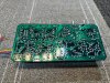
photo_2023-03-29_22-47-50 (2).jpg photo_2023-03-29_22-47-51.jpg photo_2023-03-29_22-47-52.jpg photo_2023-03-29_22-47-52 (2).jpg photo_2023-03-29_22-47-53.jpg photo_2023-03-29_22-47-53 (2).jpg photo_2023-03-29_22-47-54.jpg

photo_2023-03-29_22-47-55.jpg
 
Last edited:
I would recommend that you replace all the fuse resistors, not just the ones currently out of tolerance.

@Leestereo has a thread about restoring the 717 which includes a number of improvements on the power supply board, the eq board and the tone board. I've done several 717s, and can recommend his changes without reservation.
 
I would recommend that you replace all the fuse resistors, not just the ones currently out of tolerance.

@Leestereo has a thread about restoring the 717 which includes a number of improvements on the power supply board, the eq board and the tone board. I've done several 717s, and can recommend his changes without reservation.
Thanks for commenting. I replaced many of the fusible resistors, even ones that weren't out of spec. I think all of the quarter watt fusible resistors were replaced with metal film. I also referenced LeeStereo's thread multiple times during this restoration. It is a great resource!
 
Thanks for commenting. I replaced many of the fusible resistors, even ones that weren't out of spec. I think all of the quarter watt fusible resistors were replaced with metal film.

Ah...I must have misunderstood when reading about your work on the driver boards.

EDIT: It does say that you replaced out-of-tolerance fuse resistors, which some folks would read as saying thar only the ones out of tolerance need to be replaced.
 
Last edited:
Front end restoration:

After getting the equalizer / input board installed and tested, I moved to the front end of the amplifier (Flat amp, tone amp, signal switching)
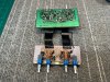
This section involved lots of contact cleaning and reflowing of boards with cracked solder joints. I attacked the small signal switching circuit boards before moving onto the tone control / flat amp board. this made it so I could work from the top down. I reflowed, defluxed, and serviced the controls on all auxiliary switching boards, and then remounted to the front sub chassis.

photo_2023-03-29_22-47-59 (2).jpg photo_2023-03-29_22-47-59.jpg photo_2023-03-29_22-47-55 (2).jpg photo_2023-03-29_22-47-57.jpg

The flat amp / tone control amp circuit board was filled with components that needed to be replaced. Lots of potentially noisy signal transistors, aging capacitors, fusible resistors, and VD-1212 diodes. Not to mention the typical terrible factory soldering...

photo_2023-03-29_22-48-01.jpg photo_2023-03-29_22-48-01 (2).jpg photo_2023-03-29_22-48-02.jpg photo_2023-03-29_22-48-02 (2).jpg photo_2023-03-29_22-48-03.jpg

photo_2023-03-29_22-48-00.jpg
 
Front end restoration:

Lots of work done to this board as mentioned above. After sitting down for a couple of hours meticulously rebuilding this board (and gain matching signal transistors), It looks great and is ready to be reinstalled into the amplifier. There were lots of upgrades on this board including removing all of the electrolytic signal coupling capacitors and replacing with film capacitors with much better characteristics for use in the signal path... Also serviced was the volume control. It wasn't noisy, but cleaning and treating will guarantee noise free operation for the next few decades anyway :)

photo_2023-03-29_22-48-08.jpg photo_2023-03-29_22-48-06 (2).jpg photo_2023-03-29_22-48-07.jpg photo_2023-03-29_22-48-05.jpg
photo_2023-03-29_22-48-03 (2).jpg photo_2023-03-29_22-48-04.jpg photo_2023-03-29_22-48-06.jpg photo_2023-03-29_22-48-09 (2).jpg

photo_2023-03-29_22-48-07 (2).jpg
photo_2023-03-29_22-48-08 (2).jpg
 
Rear I/O restoration:

After getting the front end put together and testing signal integrity, I moved to the rear section of the amplifier. I removed the circuit boards that house the input and output RCA jacks and signal switching for Pre/Main operation. Lots of dry and cracked solder joints on the boards that house the RCA jacks, and there are also a bunch of signal coupling capacitors that need to be changed out with film capacitors...

photo_2023-03-29_22-48-12.jpg photo_2023-03-29_22-48-13.jpg photo_2023-03-29_22-48-13 (2).jpg photo_2023-03-29_22-48-14.jpg
photo_2023-03-29_22-48-15.jpg photo_2023-03-29_22-48-15 (2).jpg photo_2023-03-29_22-48-17.jpg photo_2023-03-29_22-48-17 (2).jpg

After reworking the circuit boards, I polished the oxidation and corrosion off of the inside and outside of all of the RCA jacks, making them look and perform like new. I remounted the circuit boards and then moved over to replace the stock "lamp cord" style power cord with a proper IEC inlet. After getting the IEC inlet installed, I spent some time cleaning and polishing the rear plate of the amplifier, making it shine like new.

I am still waiting on replacement binding posts to arrive from EU, so I will get them installed when they arrive to me :thumbsup:

photo_2023-03-29_22-48-19.jpg
photo_2023-03-29_22-48-20.jpg
 
Cosmetics:

Upon finishing the rear I/O section of the amplifier, I moved over to the cosmetic side of the restoration. I took the faceplate to my deep sink and gave it a good cleaning with warm soapy water and a microfiber cloth. In this case, that's all that needed to be done for the faceplate and knobs / switch caps. Also done was the bottom and top covers of the amplifier.

photo_2023-03-29_22-48-20 (2).jpg photo_2023-03-29_22-48-21 (2).jpg photo_2023-03-29_22-48-21.jpg
photo_2023-03-29_22-48-22.jpg photo_2023-03-29_22-48-23.jpg photo_2023-03-29_22-48-23 (2).jpg

The faceplate and knobs / switch caps truly look like new after a gentle cleaning!

photo_2023-03-30_00-57-01.jpg
 
Finalizing the restoration:

After getting all of the internal shrouds reinstalled, securing the loose wire looms, and giving everything one last cleaning and inspection, I ran the amplifier for multiple hours and adjusted bias and offset in both channels. I am going to verify measured performance of the amplifier in the coming days, but for now, it is sounding superb. All of the background hum and hiss is no longer, which illustrates the effect of performing a restoration of this caliber.

photo_2023-03-30_01-02-36.jpg photo_2023-03-30_01-02-37.jpg photo_2023-03-29_22-48-25.jpg photo_2023-03-29_22-48-27.jpg
photo_2023-03-29_22-48-27 (2).jpg photo_2023-03-29_22-48-28.jpg photo_2023-03-29_22-48-24.jpg photo_2023-03-29_22-48-29.jpg

photo_2023-03-30_01-02-34.jpg

Thanks for viewing! I will be sure to update this thread with the measured performance numbers of this amplifier, as well as pictures of the binding posts when I receive and install them. As mentioned before, I will also be uploading a video to YouTube showcasing the work done during this restoration (Over an hour long video!) So keep an eye out for that!

Big thanks to @Leestereo and @Super Noob for providing ever-helpful informational threads on Sansui AU-717's that can be found here and here!
Also a massive thanks to my great friend @Will_Emanuel for providing me with a helpful BOM to reference!
 
Last edited:
A small rant about the misnomer of a "restoration":

One of my biggest pet peeves in the audio world is the common practice of dramatizing work done to audio gear. This is usually done to artificially and disingenuously drive the price of gear on the second hand market up. Many people believe that a "restoration" only includes spraying deoxit into the potentiometers, cleaning the faceplate, blowing dust bunnies out of said piece of equipment, and less frequently, a basic recap. This is very far from the truth, and usually puts honest technicians like myself in a bad spot when confronted about why it takes as long as it does for a thorough restoration. Audio gear of this age suffers from much more than the typical bad capacitors, and usually requires specialized service to guarantee the stability of the unit overtime. Again, the term comprehensive servicing comes into play again. Remember this.

What I believe a "restoration" is:

In my eyes, a restoration is where a piece of equipment is brought back to factory specifications and working condition (or better) both inside and out. This is accomplished by addressing every issue both known and observed. Things such as removing corrosive glue, reflowing and defluxing circuit boards, replacing capacitors and known problematic signal transistors, regulators, diodes, and addressing heat related issues such as PCB and trace damage, remounting outputs and drivers on new thermal interfaces, and even a thorough cleaning. There are more steps to take than this, especially depending on what it is to be worked on, but you get the idea. There is much more to a "restoration" than what most eBay sellers would lead you to believe.

Hear, hear!

Currently working on my own 717. Last night, I removed the source selector switch and cleaned the switch poles. No amount of DeOxit will keep these from getting noisy again, unless you have it on an IV drip going into the switch. The corrosion/tarnish will always keep advancing after cleaning, so the cure is to remove as much of it as you can, and for that you need to open the switch up. Tonight I may do the record out switch, or perhaps over the weekend.

Cut and pasted from another thread I replied on. On the power supply boards, there is usually a resistor or two that have the glue contamination. Most people would replace just these. But we're dealing with a whole system here, now you have a modern metal film resistor sitting in with a bunch of old carbon resistors? Doesn't seem good to me. I replaced all the resistors in that regulated supply section with 1% metal films.

Not removing output transistors and re-greasing them is my pet peeve. And not replacing the old trimmers is another one.
 
Hear, hear!

Currently working on my own 717. Last night, I removed the source selector switch and cleaned the switch poles. No amount of DeOxit will keep these from getting noisy again, unless you have it on an IV drip going into the switch. The corrosion/tarnish will always keep advancing after cleaning, so the cure is to remove as much of it as you can, and for that you need to open the switch up. Tonight I may do the record out switch, or perhaps over the weekend.

Cut and pasted from another thread I replied on. On the power supply boards, there is usually a resistor or two that have the glue contamination. Most people would replace just these. But we're dealing with a whole system here, now you have a modern metal film resistor sitting in with a bunch of old carbon resistors? Doesn't seem good to me. I replaced all the resistors in that regulated supply section with 1% metal films.

Not removing output transistors and re-greasing them is my pet peeve. And not replacing the old trimmers is another one.
Hear, hear! ;)
 
Last edited:
@Connor G: Very nice work!

If I may, a quick comment regarding the replacements for C27/C29 and C28/C30 on the phono board (F-2723): these 10uF capacitor pairs are arranged in series and can be replaced by a single film capacitor (~5uF), installed in place of the original film by-passes at C35 and C36.

Phono detail.jpg

F-2723 detail.jpg
F-2723 picture from this AK post
 
On the power supply boards, there is usually a resistor or two that have the glue contamination. Most people would replace just these. But we're dealing with a whole system here, now you have a modern metal film resistor sitting in with a bunch of old carbon resistors? Doesn't seem good to me. I replaced all the resistors in that regulated supply section with 1% metal films.
If the resistors used here were pure carbon composition types, I would have replaced them with metal film. But seeing as they are all carbon film resistors, their noise and thermal characteristics are such that I believe it would be mostly unnecessary to replace them as they wouldn’t improve any noise or thermal stability characteristics of the amplifier. Sure, it could be done, but that would add an immense amount of work / time (and therefore cost) to the restoration that the owner likely wouldn’t want to pay, especially for little to no improvement, especially since the power supply runs very cool after the restoration and modification. Good luck and have fun with your restoration! These really are a treat to work on :)
 
Back
Top Bottom