• The move to the new server is done. There are some software and database maintenance updates in process. This has us passing the hat around to help out. We appreciate any donations. Seriously, even a dollar helps. The payment page may be found here - https://www.audiokarma.org/support.html

Sansui AU-719: how does the protection work?

PE9ZZ

Event Horizon
Subscriber
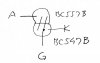
I have this amp on my workbench and it went into protect after some time. As per complaint. The thyristor SCR601 was bad. I should have replaced it with a replacement (MCR100) but since this was not present in my tray and there is time pressure I replaced it with a DIY thyristor consisting of an NPN (BC547B) and a PNP (BC557B) transistor (image Wackypedia):
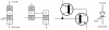
Thyristor.svg.png

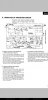
While this seems to have solved the problem (still need to do the soak test to confirm) I cannot figure out how this circuit is supposed to work. Very helpfully Sansui included this block diagram but failed to provide an explanation:
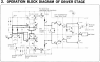
3.png

Question is: how does it work? Is it sensing the driver going into clipping, detecting high frequency components associated with clipping or something I am overlooking? In other words: what is TR17 detecting?
 
Register to hide this ad
It is even worse: it is fundamentally different. The 517/717 uses a sense transistor (TR09) across an emitter resistor of the output stage (R44). The 719 does its mystery detecting in the driver stage and is capacitively coupled.
 
its not the same .
I am a novice at electronics. And your right it is not the same, with the same idea I meant : detecting DC; detecting excessive current from the driver board. Because you where asking about clipping detection.
But you're in good hands because @PE9ZZ is a professional. So I am going to keep following your thread and hope he can give an explanation that I as a novice can understand.
 
and is capacitively coupled.
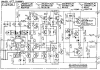
If you look at the schematic rather than the block diagram, you will see that its input at least, is DC coupled - with a 100KΩ resistor. The capacitive coupling at the output (C24, 1µF) must mean that a sharp voltage change (when TR17 turns on), passes through the capacitor as a 'spike' - and latches the Thyristor on, which after a series of events opens the protection relay. I also think TR17 is 'detecting' the B-E voltage of TR701, and the voltage drop across R52 (0.33Ω).
 
If you look at the schematic rather than the block diagram, you will see that its input at least, is DC coupled - with a 100KΩ resistor.
You're right. It only works if the output is shorted to ground. The voltage developed across R52 lifts the B-E junction of TR701, forward biasing TR17's B-E junction, turning it on. The resulting spike triggers the thyristor and this locks the amp into protect. A regular clipping doesn't do that because TR17 will be blocked by D05. Also D03 will bleed base drive away to ground.

f-2926.png

See PDF for bigger pic.

My thyristor kludge is a bit too sensitive and sometimes triggers at poweron. Hmmmm...
 

Attachments

Got it sorted. Reduced R610 from 1k to 820R and this solved the go-into-protect-at-poweron issue. The final test, the short circuit test, was PASS. I am always a bit nervous doing this test...
 
This is the DIY thyristor schematic:
diy_thyristor_sch.jpg

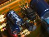
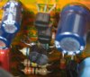
This is how it turned out:
scr601-1.jpg

scr601-2.jpg

The turquoise resistor beneath the DIY thyristor is R610, lowered in value from 1k to 820R.
 
Back
Top Bottom