• The move to the new server is done. There are some software and database maintenance updates in process. This has us passing the hat around to help out. We appreciate any donations. Seriously, even a dollar helps. The payment page may be found here - https://www.audiokarma.org/support.html

Sansui AU-719 Protection Problem

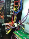
Thought 1. Yes someone was making a mess of things. For example, all of the primary wires on the two transformers were connected together using orange wire
nuts used in electrical house wiring. I have been wire checking all the power, ground and signal wiring and have verified very low resistance readings back to the power supply board.

Thought 2. Good point. Will do and report back to you.

Thought3. I also restore Tube Amps, so I'm very carefully when probing any live circuitry.

Thought 4. Yes, I did verify that VR01 measured 100 ohms and that VR02 measured 480 ohms.

Thought 5. Yes, I have been testing with the tone controls disabled and the input set to AUX. I also understand from the AK threads, that the input must be in PHONO
when testing the Phono EQ board. Is that correct?

Using my Amp's serial number 229091353, how can I determine if my model is a USA, EU, CAN, or JAPAN unit?

My Service Manual's Driver Board Block Diagram shows two triple diodes one in each of the collectors of TR 10 and TR 12, yet my amp doesn't have these diodes installed.
That's why I'm asking about where my amp was built, different countries different designs?

Thanks for your thoughts, they are most helpful.

Bob
 
Thought 5. Yes, I have been testing with the tone controls disabled and the input set to AUX. I also understand from the AK threads, that the input must be in PHONO
when testing the Phono EQ board. Is that correct?

Certainly to couple audio signal to the amp boards this is true, but the EQ board is powered all the time so you can do quite a bit of testing otherwise. Interestingly the EQ 0V adjustment instructions make no mention of the input selection and looking at the schematic, it should make no difference for the adjustment.

Using my Amp's serial number 229091353, how can I determine if my model is a USA, EU, CAN, or JAPAN unit?

This is maybe a question for @LBPete but my guess is you don't know from the serial number. My 719 has the typical voltage sticker on the back panel that tells you what voltage was selected at the factory. Since someone was messing around with the transformer wiring it's probably worth looking at the selector under the bottom panel to verify that the voltage selection plug is in the correct spot. I haven't seen a non-U.S. unit so I don't know if there's another indication.

My Service Manual's Driver Board Block Diagram shows two triple diodes one in each of the collectors of TR 10 and TR 12, yet my amp doesn't have these diodes installed.
That's why I'm asking about where my amp was built, different countries different designs?

My SM shows the same in the block diagram but I wouldn't put too much store in the absolute accuracy of that diagram since they also show double diodes instead of triples on the input JFET Drains.


I would definitely double verify those wire nut transformer connections, then change to soldered and insulated, UGH.
 
My Service Manual's Driver Board Block Diagram shows two triple diodes one in each of the collectors of TR 10 and TR 12, yet my amp doesn't have these diodes installed.
That block diagram is incorrect, rely on the schematic for the presence of components, also don't alter the components in your unit to agree with the schematic - as these were issued very early in the production cycle and production changes never got updated.

That's why I'm asking about where my amp was built, different countries different designs?
There are often minor changes, but these are usually confined to the mains wiring and voltage ratings, fuse current ratings or values of some components. @LBPete will very likely know how to identify your unit.

I am thinking that if you could check the bias current and try to adjust it, you would find out if it is just 'miss-set' or if you have high current draw for another reason. At the moment, you seem to have a Kill-A-Watt, a Variac and a DBT in circuit, which is protecting your unit from damage, but it is significantly muddying the waters when it comes to voltage readings and meaningful fault finding.

If the internal mains wiring has been interfered with, that is now your number one priority to get corrected before you do anything else. And as wisely recommended, carefully check the wiring and get rid of those wire nuts.
 
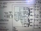
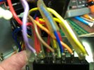
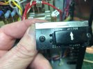
I attached photos showing the existing primary transformer windings wiring and the voltage selector switches wiring (which looks factory original). The primary transformer wiring and the voltage selector switch wiring agrees with the attached schematic shown. With both driver boards out of the circuit, using a Variac I raised the AC input voltage to 120 v AC and the Amp came out of protection and I measured +/- 63 v DC on the rails. So the number one priority to prove that the AC input wiring is correct has been done.

How do I proceed with taking voltage readings and meaningful fault finding? Just using the Variac and monitoring the fault current? Would that work? I don’t want to cause any damage to the amp at this point.
 

Attachments

  • IMG_6407.jpeg
    IMG_6407.jpeg
    171.2 KB · Views: 10
  • IMG_6408.jpeg
    IMG_6408.jpeg
    177 KB · Views: 9
  • IMG_6406.jpeg
    IMG_6406.jpeg
    211.4 KB · Views: 8
  • IMG_6402.jpeg
    IMG_6402.jpeg
    131.5 KB · Views: 8
  • IMG_6405.jpeg
    IMG_6405.jpeg
    138.6 KB · Views: 9
and I measured +/- 63 v DC on the rails.
Excellent - progress.

How do I proceed with taking voltage readings and meaningful fault finding? Just using the Variac and monitoring the fault current? Would that work? I don’t want to cause any damage to the amp at this point.
Can I assume that this was with the amplifier driver modules not installed?

You could reconnect them - one at a time and try the long requested bias current check, you can connect your meter to the bias current check points, and power up, (ideally at this stage without the variac), but include the variac for the first power up just to see what's going on. If the current is not excessive and you can turn the variac up to 'full mains' (but on DBT), you can try adjusting the bias (and DC offset), you should be able to see the DBT bulb dimming as you turn the bias down (or vice versa) - if this is successful, still with only one driver module connected then you can try with only the DBT, but get ready on the power switch to power off immediately if the current suddenly increases. (NB: no load needed on the output).

If all the above is successful, you could reconnect only the other driver module and repeat the process.

If none of this works as expected and you still have uncontrollably high current draw - then you need to thoroughly recheck your work on the driver modules. I would remove and recheck all the semiconductors, for type number, orientation and functionality using a transistor tester. And all electrolytics for orientation - especially the big ones. Don't forget that some electrolytics (on the negative supply) may be connected with their positive to ground.
 
Last edited:
Yes, in my post I indicated that “ With both driver boards out of the circuit…” ,I performed the test.

Previously, I have tried bias and offset adjustments, but I was always getting a high voltage on the both driver boards outputs and could only lower it several volts. For example, during the bias test with +/- 10 v DC applied to the rails, I had + 8.6 v DC (it was always a “+” voltage DC on either driver boards outputs,) I could only adjust the bias voltage to + 6.6 v DC.
It was pointed out to me that the rail voltages should > +/- 13 v DC for correct operation of ZD02. I was about to do this bias test again when I decided to recheck the mains primary input wiring to ensure it was wired correctly.

Now, I will the perform the bias and offset tests at the higher rail voltage following your test procedure, as outlined above.

Thanks again for all your input, I appreciate it.

Bob
 
Using my Amp's serial number 229091353, how can I determine if my model is a USA, EU, CAN, or JAPAN unit?
That information isn't coded into the serial number. The ID plate on the back of the unit will indicate what input voltages the amp is designed to accept. In this time period, most will be "General Export Models" and the ID plate will list 4 voltages: 100, 117, 220, 240. Hope this helps

Regional models will list specific voltages. Japanese Domestic (JDM) models will indicate 100V, North American (USA, Canada, Mexico) models will indicate 117V. European models will indicate 220/240v and will not have the 2 blade "North American" accessory outlets on the back panel.

What your serial number does indicate is your AU-719 was built on production line 22 in September of 1979. It was the 1,353rd unit off that line that month. Looking at the database Line 22 was also building AU-D907 Limiteds, AU-919s and AU-519s in addition to AU-719s that month.

- Oete
 
Hi,

Can anyone please recommend where I can purchase these bayonet style connectors for the driver board output transistors as shown in the attached photo? Or possibly suggest an other method of connecting the output transistors wiring to the driver board, if these connectors are unavailable?
Thanks,

Bob
 

Attachments

  • IMG_0398.jpeg
    IMG_0398.jpeg
    97.9 KB · Views: 12
Here's an alternative option to make your choice more difficult :).

TE Connectivity also makes the very similar 170338-1 which seems a little more flexible in application, but the big draw for me is that it stands only about half as high above the board surface as the one @Hyperion pointed out. I tend to be fairly ham handed moving things around in the chassis so I like that I'm less likely to bend the shorter connectors and there's less exposed conductor sticking up in the air.

 
I have purchase both of the above .
The problem is that it is one time soldering, if you remove it from the board it will break.
The quality that Sansui used its unparalleled.
 
Thanks Hyperion for your quick response to my request, it’s greatly appreciated.

It turns out while adjusting the offset on the F2926 driver board the amp finally came out of protection. Unfortunately, the DBT suddenly brightened and the amp went into protection and I immediately shut the amp off.
Found an open in the orange wire on the bayonet connector that connects to terminal 05 on the F2926 PCB. That’s the Base of TR 701 output transistor.

The connectors are on order from Mouser, and I plan on replacing all the output transistor’s connectors and wiring asap.

Bob
 
Agreed, Sansui’s connectors are definitely top-notch. Wish I could somehow recycle them. By the way, the existing output transistor wiring is 20 awg would 18 awg be a better choice?

I also noticed on all the original factory wiring of all of the output transistor’s except the TR 701 transistor, that the bayonet’s crimp closer to the wire end crimps both insulation and wire together while the other crimp just crimps the conductor. On TR 701’s three wires only the conductor was crimped by both crimps of the bayonet. It appears that the stranded wire on all three bayonet’s were damaged with the “base” wire being the worse of the bunch.

Bob
 
One option is to cut off and strip a clean longer bit of wire, like ~6mm, insert it thought the hole in the board until the insulation hits and bend it on the backside before soldering.
I usually manage to pull these out and reinsert them though. But you need to suck all the solder from the board, clean the hole and clean the pin.
Then it usually works fine to reinsert with a little bit of force while also heating the pin with the soldering iron. (Yes you need three hands for this or plenty of practice :-) ).
 
I usually manage to pull these out and reinsert them though. But you need to suck all the solder from the board, clean the hole and clean the pin.
Then it usually works fine to reinsert with a little bit of force while also heating the pin with the soldering iron. (Yes you need three hands for this or plenty of practice :-) ).
I've had good luck re-inserting the oem connectors by heating the bare connector and letting the wire tension flick the melted solder out of the connector before replacing in the hole. Just be sure to make the flick aim away from the 'operator', experience is the best teacher :yikes:

I have not needed to remove one of those TE connectors I mentioned above so can't speak to the re-usability. The shorter version I pointed to does accept a wider range of wire size so that one would support changing to 18ga if you make that choice
 
Thanks to all for the info.
I’ve ordered some of both connectors to have the option for installing 18 awg wire.
I’ve been using the Hakko desoldering tool and small soldering wick to clean the bayonets and pad holes with decent results.
 
Just for info, I don't have a crimp tool for those terminals. So I strip and tin the wire, then use pliers to fold over the wire clamps gripping the wire, then solder the connection. Finally, I tighten the smaller (top) wire insulation grip using pliers again.

(Somewhere on AK there is a picture I posted of a completed terminal, done with the procedure above ;))

Here is the picture, not very clear (and a slightly different style terminal in use here), but you get the general idea. (from my AU-9900 restore, 15 years ago ;))

(more info if you search in 'Exclusively Sansui' for crimp terminals, and my username).

1775461044403.png
 
Last edited:
I always like to solder crimp connections, if possible. Thanks for your procedure, I will definitely use it and checkout the completed terminal picture on AK.
 
Back
Top Bottom