

You are using an out of date browser. It may not display this or other websites correctly.
You should upgrade or use an alternative browser.
You should upgrade or use an alternative browser.
Sansui AU-719 Protection Problem
- Thread starter bobpep
- Start date

Hi,
Finally getting some bench time in quite a while.
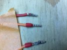
The attached photo shows three different connections for the output transistors. Has anyone tried crimped ferrules in a case like this?
The top connection in the photo is the traditional bayonet one.
The middle connection is crimped only (this ferrule connector is 18 awg and nicely fits the PCB terminal.)
And the bottom one is all three in one.
Also, can anyone recommend a high temperature epoxy for a partially lifted pad on one of the output transistor connections, or should I just run a wire?
Thanks.
Bob
Finally getting some bench time in quite a while.
The attached photo shows three different connections for the output transistors. Has anyone tried crimped ferrules in a case like this?
The top connection in the photo is the traditional bayonet one.
The middle connection is crimped only (this ferrule connector is 18 awg and nicely fits the PCB terminal.)
And the bottom one is all three in one.
Also, can anyone recommend a high temperature epoxy for a partially lifted pad on one of the output transistor connections, or should I just run a wire?
Thanks.
Bob
Attachments
Also, can anyone recommend a high temperature epoxy for a partially lifted pad on one of the output transistor connections, or should I just run a wire?
Thanks.
I haven't tried a ferrule, but that's a very intriguing solution. I'll need to try it next time around.
Finally, replaced all of the output transistors wiring and Sil-pads (upgraded to 18 gauge wire as were the connectors) on the amp. Before powering up the amp, I adjusted all the VR's per the SM.
Initially, the amp was started up using the DBT, it came out of protect and the bulb brightened and dimmed out.
Removed the DBT, and connected two DMM's for the bias adjustment. Raised the AC input voltage using a Variac and monitored the DMM's, they were reading 2-3 millivolts when the AC input voltage equaled 120v AC and the amp came out of protect. After the amp warmed up for several minutes, both channels were adjusted to 23 millivolts.
Connected the two DMM's to the Left and Right Speaker outputs for the DC offset adjustment, found 1 to 1.5 volts DC on the DMM's. Before I could make any adjustments, the amp went into protect and it was turned off.
Disconnected, both left and right channel output amps, and was able to bring the amp up and out of protection using the DBT. The bulb barely brightened then dimmed and all DC rail voltages measured normally.
The right channel output amp passed the DBT and the amp came out of protection. The left channel output amp failed the test.
Currently, checking the left channel output amp on the bench and have found no problems yet.
Any thoughts or ideas on how to proceed are most welcome.
Thanks, Bob
Initially, the amp was started up using the DBT, it came out of protect and the bulb brightened and dimmed out.
Removed the DBT, and connected two DMM's for the bias adjustment. Raised the AC input voltage using a Variac and monitored the DMM's, they were reading 2-3 millivolts when the AC input voltage equaled 120v AC and the amp came out of protect. After the amp warmed up for several minutes, both channels were adjusted to 23 millivolts.
Connected the two DMM's to the Left and Right Speaker outputs for the DC offset adjustment, found 1 to 1.5 volts DC on the DMM's. Before I could make any adjustments, the amp went into protect and it was turned off.
Disconnected, both left and right channel output amps, and was able to bring the amp up and out of protection using the DBT. The bulb barely brightened then dimmed and all DC rail voltages measured normally.
The right channel output amp passed the DBT and the amp came out of protection. The left channel output amp failed the test.
Currently, checking the left channel output amp on the bench and have found no problems yet.
Any thoughts or ideas on how to proceed are most welcome.
Thanks, Bob

Going into 'Protection Mode' is normal if there is 1-1.5V on the speaker outputs.
You need to measure the DC offset voltage before it gets to the speaker terminals - conveniently, and for a rough adjustment only - you can use either of the bias test points for each channel, measuring the voltage between either test point (for each channel) and chassis ground, then adjust DC offset to zero. Then you can swap your probes to the speaker terminals to make a fine adjustment to complete the job.
You need to measure the DC offset voltage before it gets to the speaker terminals - conveniently, and for a rough adjustment only - you can use either of the bias test points for each channel, measuring the voltage between either test point (for each channel) and chassis ground, then adjust DC offset to zero. Then you can swap your probes to the speaker terminals to make a fine adjustment to complete the job.

Set the DC offset and bias while still on DBT. Set bias to a low value or even zero.
Then remove DBT and repeat. You can then dial bias up when not on DBT.
Then remove DBT and repeat. You can then dial bias up when not on DBT.
Success. The following readings are without the DBT. I used the DBT initially as suggested adjusting the readings to the low side which worked out well.
Left Channel
Offset = - 4 mv (on the speaker terminals)
Bias = 23 mv
Right Channel
Offset = -3 mv (on the speaker terminals)
Bias = 22 mv
Is there anything special about adjusting the preamp? Also, are there multiturn pots available for this amp? It sure would make it easier to adjust the readings.
Bob
Left Channel
Offset = - 4 mv (on the speaker terminals)
Bias = 23 mv
Right Channel
Offset = -3 mv (on the speaker terminals)
Bias = 22 mv
Is there anything special about adjusting the preamp? Also, are there multiturn pots available for this amp? It sure would make it easier to adjust the readings.
Bob
Definitely, but for the 2 for the Phono amp (EQ) you have to get 'side adjust' trimmers and position them quite precisely so you can adjust them from the top of the amp (the originals allow adjustment through holes in the PCB from the side). Also it's normal not to be able to set these particular trimmers to exactly 0V, as the offset setting varies with temperature quite a lot.Also, are there multiturn pots available for this amp? It sure would make it easier to adjust the readings.
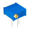
The other 4 on the power amp can also be 'side adjust' - the Bourns type number for this type of trimmer is 3296P - which is 'multi turn'.
Like this
Last edited:
Thanks for the update on the Bourns trimmers, I will definitely look into replacing the current trimmers with them.
On the Phono amp (EQ) trimmer offset adjustment what is an expected 'ballpark' reading since it is so temperature dependent?
Also, is it worthwhile to add high quality 1-2 uf film bypass capacitors across the main power supply capacitors on this amp?
Thanks again for all your help.
On the Phono amp (EQ) trimmer offset adjustment what is an expected 'ballpark' reading since it is so temperature dependent?
Also, is it worthwhile to add high quality 1-2 uf film bypass capacitors across the main power supply capacitors on this amp?
Thanks again for all your help.
Just set it as low as you can, anywhere less than say ~50mV - then after a 30 minute warm-up check it and re-adjust - that's about as good as you can get it.On the Phono amp (EQ) trimmer offset adjustment what is an expected 'ballpark' reading since it is so temperature dependent?
Some people think it is beneficial, others not. If Sansui put them there originally I tend to follow that, maybe installing better replacements. They are supposed to damp the effects of stray inductance from the main filter capacitors, which if they are good enough quality probably don't need the film by-pass capacitors.Also, is it worthwhile to add high quality 1-2 uf film bypass capacitors across the main power supply capacitors on this amp?